System and Method for Polarization Compensation

Inactive Publication Date: 2017-11-30
AEVA INC
View PDF3 Cites 7 Cited by
  • Summary
  • Abstract
  • Description
  • Claims
  • Application Information

AI Technical Summary

Benefits of technology

[0007]Various implementations of the invention, improve an optical efficiency of an optical path comprising a polarizing beam splitter and a quarter wave plate. In some implementations of the invention, where an additional optical component introduces a phase retardance into the optical path, the quarter wave plate may be adjusted away from its nominal orientation relative to the optical path to improve an optical efficiency of the optical path. In some implementations of the invention, the quarter wave p

Problems solved by technology

For systems having two or more such components, the accumulative retardance can easily exceed 45°, and the optical efficien

Method used


Image

  • System and Method for Polarization Compensation
  • System and Method for Polarization Compensation
  • System and Method for Polarization Compensation

Examples


Embodiment Construction

[0016]Chirped lidar systems employ two or more laser sources to provide chirped lidar signals. These chirped lidar signals, when incident upon and reflected back from a point on a target, may be detected and used to determine a range and an instantaneous Doppler velocity of the point on the target. Such a lidar system is available from Digital Signal Corporation of Chantilly, Va., and is described in its U.S. Pat. No. 7,511,824, entitled “Chirped Coherent Laser Radar System and Method,” which issued on Mar. 31, 2009. The foregoing patent is incorporated herein by reference as if reproduced below in its entirety.

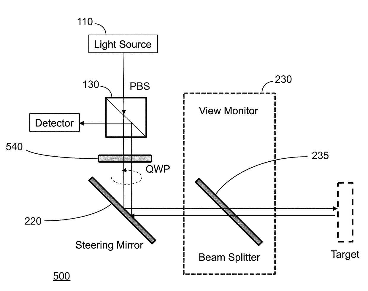
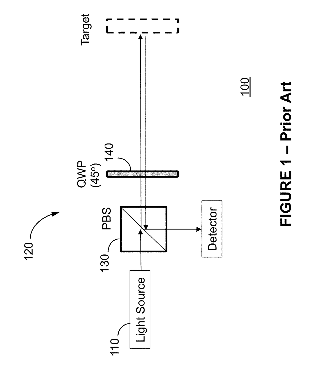
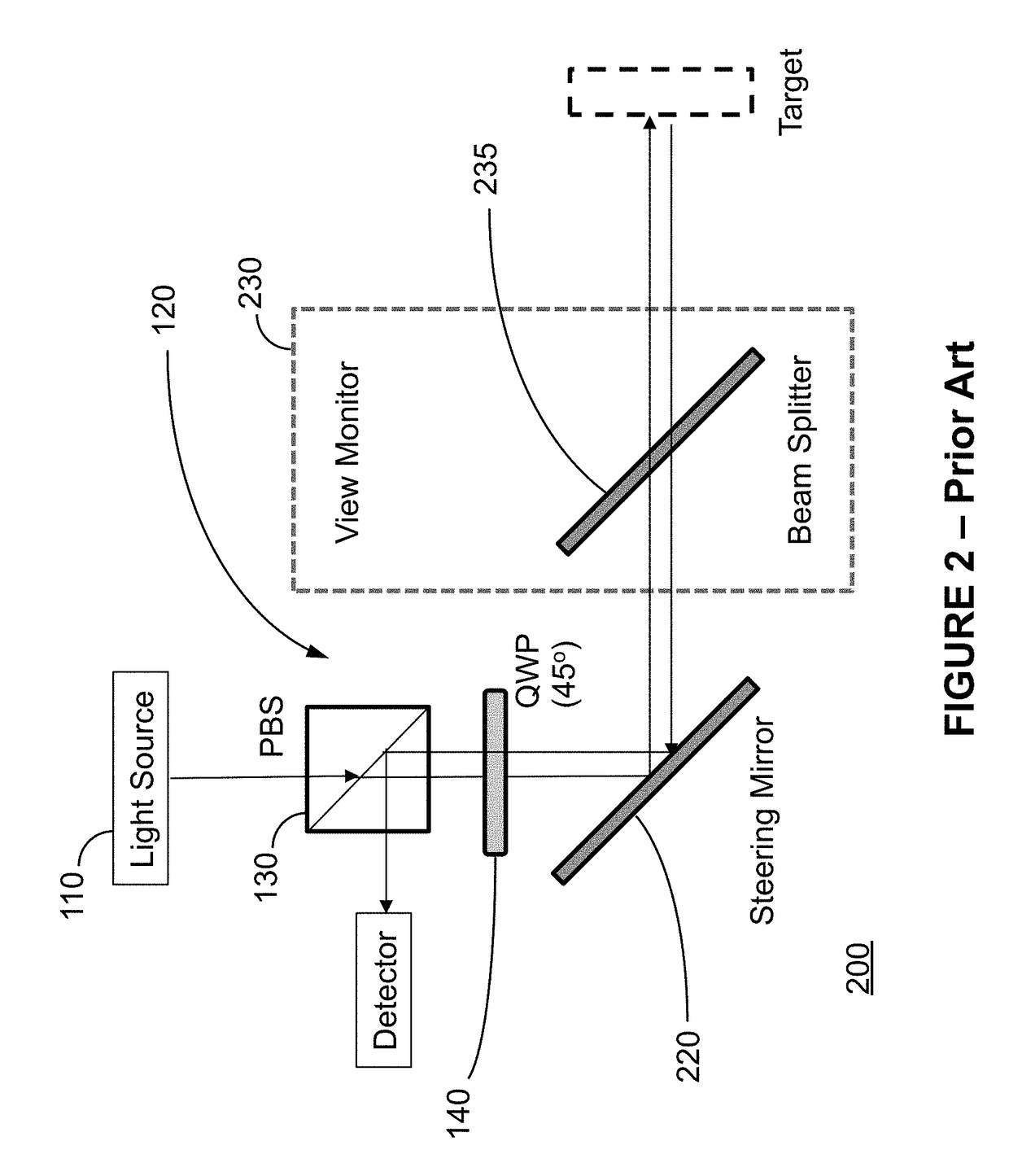
[0017]The lidar system referenced above (which may be considered a transmitter / receiver for purposes of this description) employs linear polarization for the optical path comprising a majority of the optical components and fibers (i.e., fiber optics) and circular polarization for the optical path of free space from the lidar system to a target and back (i.e. free-space path)....


PUM


Abstract

Various implementations of the invention, improve an optical efficiency of an optical path comprising a polarizing beam splitter and a quarter wave plate. In some implementations of the invention, where an additional optical component introduces a phase retardance into the optical path, the quarter wave plate may be adjusted away from its nominal orientation relative to the optical path to improve an optical efficiency of the optical path.

Description

CROSS-REFERENCE TO RELATED APPLICATIONS[0001]This Application claims priority to U.S. Provisional Application No. 62 / 279,093, which was filed on Jan. 15, 2016, and entitled “System and Method for Polarization Compensation.” The foregoing application is incorporated herein by reference in its entirety.FIELD OF THE INVENTION[0002]The invention is generally related to circular polarization in an optical transmitter / receiver system (e.g., laser radar system or lidar), and more particularly, to compensating for optical components that introduce phase retardance in a circularly polarized optical path of the transmitter / receiver system.BACKGROUND OF THE INVENTION[0003]Various conventional transmitter / receiver systems, including, but not limited to laser radar systems, employ circular polarization to improve, optimize, and / or maximize an optical efficiency of such systems. FIG. 1 illustrates a conventional configuration of a transmitter / receiver system 100 incorporating a circular polarizer...

Claims


Application Information

Patent Timeline
IPC IPC(8): G02B5/30G02B27/28G01S7/499
CPCG02B5/3083G01S7/499G02B27/283G01S7/4812
Inventor WAN, XIAOKEDANIEL, HANIROLLER, CHRIS
Owner AEVA INC
Why Eureka
Try Eureka