Light guide plate, method for manufacturing light guide plate, and image display device using same

Pending Publication Date: 2021-06-03
HITACHI-LG DATA STORAGE
View PDF0 Cites 0 Cited by
  • Summary
  • Abstract
  • Description
  • Claims
  • Application Information

AI Technical Summary

Benefits of technology

[0017]According to the present invention, a waveguide which improves optical efficiency, a method

Problems solved by technology

Although a half mirror can be used as the waveguide, it was difficult to red

Method used


Image

  • Light guide plate, method for manufacturing light guide plate, and image display device using same
  • Light guide plate, method for manufacturing light guide plate, and image display device using same
  • Light guide plate, method for manufacturing light guide plate, and image display device using same

Examples


Example

Embodiment 1

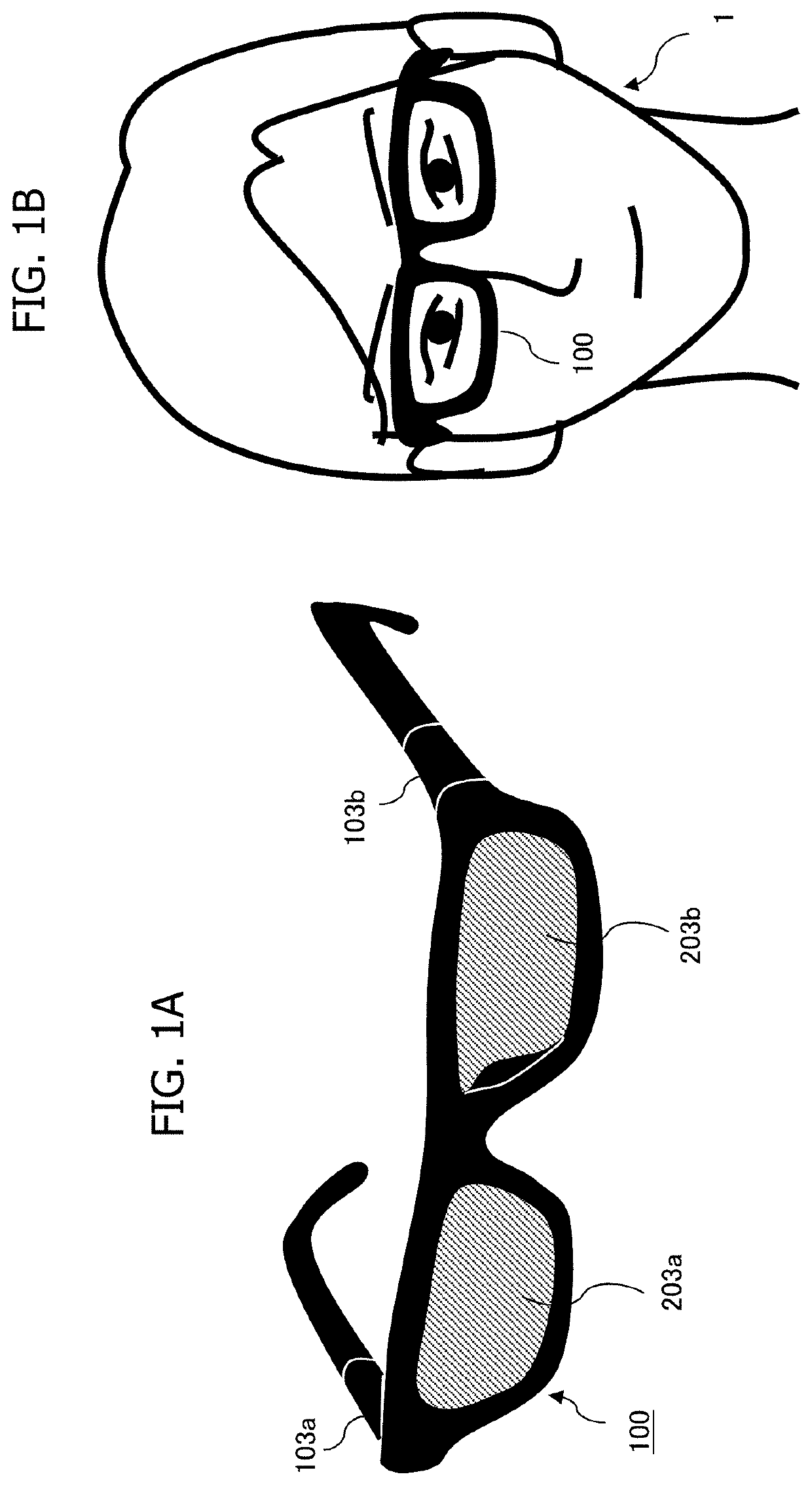
[0036]FIG. 1A is an appearance diagram of an image display device according to this embodiment. Further, FIG. 1B is an appearance diagram illustrating a usage example of the image display device.

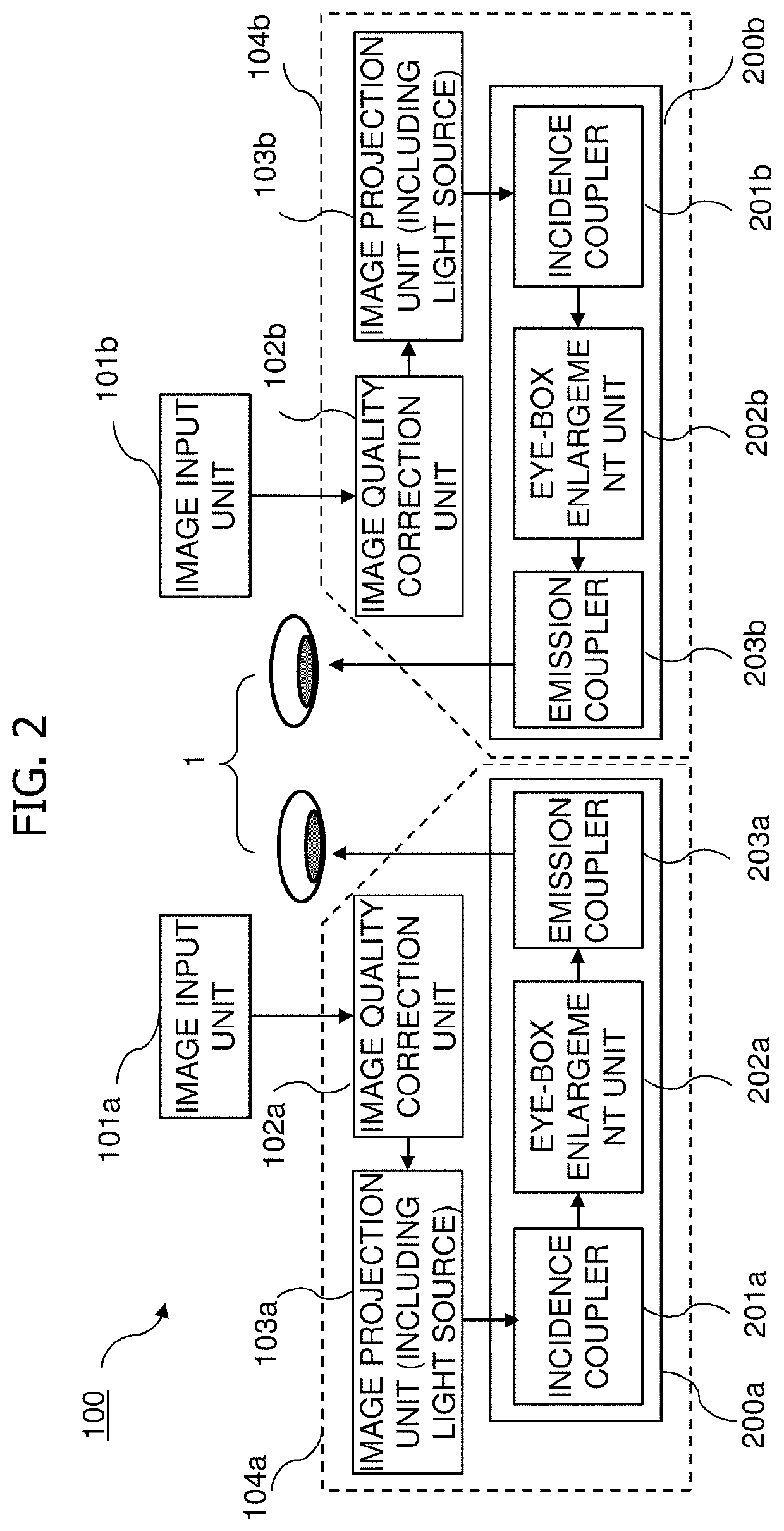
[0037]In FIG. 1A, a glasses-type image display device (HMD) 100 includes an image projection unit 103a that projects an image to be displayed on the right eye of a user 1 and an image projection unit 103b that projects an image to be displayed on the left eye of the user 1, in the portions corresponding to temples of the glasses. Further, emission couplers 203a and 203b for delivering the images projected by the image projection units 103a and 103b to the eyes of the user 1 are provided on the portions corresponding to the lenses of the glasses. The emission couplers 203a and 203b can not only display an image but also transmit light from the outside world, and can display augmented reality (AR) to be shown to the user by superimposing the image on the outside world. As illustrat...

Example

Embodiment 2

[0095]FIG. 12 illustrates a configuration of a waveguide in this embodiment. In this embodiment, the optical efficiency is improved by using a multi-layer structure instead of the region division. In FIG. 12, the waveguide 200 has a four-layer structure, and volume holograms that diffract a set of different wavelengths with respect to a light ray of a certain angle are recorded in each layer. Each layer includes an incidence coupler 1200 and an emission coupler 1210, and in each layer, a pair of input and emission couplers has a configuration in which volume holograms recorded at the same angle are arranged symmetrically. With this, a combination of an angle and a wavelength of a light ray diffracted by the incidence coupler and incident on the waveguide and a combination of the angle and the wavelength of the light ray diffracted by the emission coupler and emitted to the outside of the waveguide match, and the loss of light is minimized. Further, when the light ray ang...


PUM


Abstract

The purpose of the present invention is to provide a waveguide, a method for manufacturing the waveguide, and an image display device using the same, which can be applied to incident light with a wide light angle range and a wide wavelength range, and can suppress a decrease in optical efficiency while maintaining high see-through performance. In order to achieve the above purpose, the waveguide has a light diffraction unit that diffracts the incident light by a multiplex-recorded hologram, wherein the light diffraction unit has at least two regions, and the light diffraction unit diffracts light of different wavelengths by the respective regions when certain parallel light ray is incident.

Description

TECHNICAL FIELD[0001]The present invention relates to a waveguide used for an image display device such as a head mounted display.BACKGROUND ART[0002]In the image display device such as a head mounted display (HMD), a waveguide is used as an optical system for propagating image light emitted from a projector (image projection unit) to the eyes of a user. It is desirable that the waveguide used for the HMD be thin and have a wide field of view (FoV) through which an image can be seen. Although a half mirror can be used as the waveguide, it was difficult to reduce the thickness of the waveguide in order to secure the wide field of view.[0003]As a background art related to this, Patent Documents 1 and 2 describe a special mirror or half mirror (called a “skew mirror” in the documents) in which a reflection axis has an inclination with respect to a surface normal by using a hologram technique. When the skew mirror is adopted for the waveguide, the same function as that of the half mirro...

Claims


Application Information

Patent Timeline
IPC IPC(8): G02B27/01G03H1/02G03H1/26F21V8/00G02B27/00
CPCG02B27/0172G03H1/0248G03H1/2645G02B6/0038G02B2027/0178G03H2001/266G02B2027/0174G02B2027/0116G02B2027/0118G02B27/0081G02B5/32G02B6/34G02B2027/0125G03H1/265G03H1/30G03H2001/261G03H2001/262G03H2270/55G03H2223/16G03H2001/0439
Inventor UTSUGI, TAKERU
Owner HITACHI-LG DATA STORAGE
Why Eureka
Try Eureka