Micro display projection system

Inactive Publication Date: 2005-06-02
LG ELECTRONICS INC
View PDF2 Cites 0 Cited by
  • Summary
  • Abstract
  • Description
  • Claims
  • Application Information

AI Technical Summary

Benefits of technology

[0023] The present invention can optimize the polarization ratio of the polarization beam splitter to improve the performance of the polarization beam splitter even at a small f-number. Furthermore, the present invention can improve the optical effici

Problems solved by technology

Recently, display systems have become light and thin while having a large screen.
However, even when the aperture ratio is maintained using the reflection-type liquid crystal display panel, the reduced size of the liquid crystal display panel decreases the Etendue

Method used


Image

  • Micro display projection system
  • Micro display projection system
  • Micro display projection system

Examples


Embodiment Construction

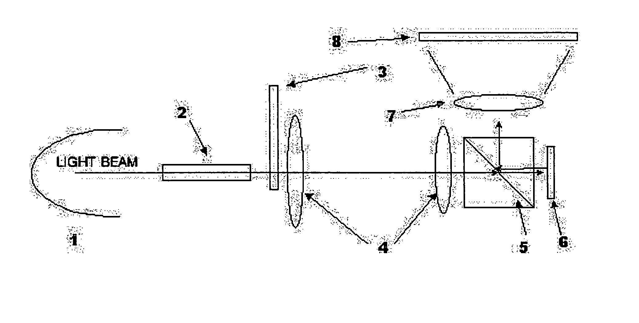
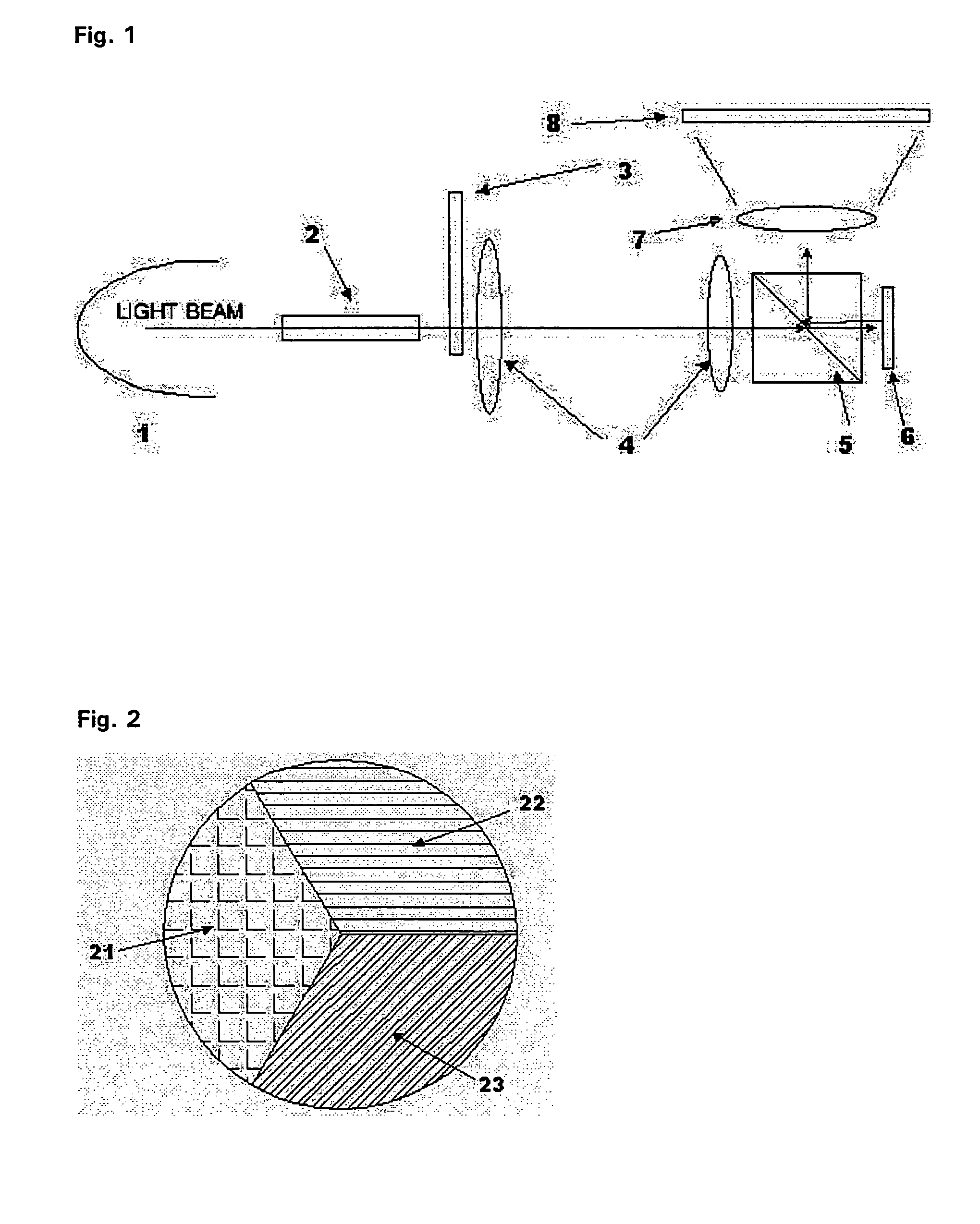
[0031] Preferred embodiments of the present invention will be described in a more detailed manner with reference to the drawings.

[0032] A reflection-type micro display projection system according to the present invention includes a light source for emitting a light beam, an optical system for transmitting the light beam emitted from the light source, a reflection-type liquid crystal display panel for reflecting the light beam transmitted through the optical system and outputting the light beam as image information, a projection lens for magnifying and projecting the image information, and a screen for displaying an image corresponding to the image information magnified and projected by the projection lens.

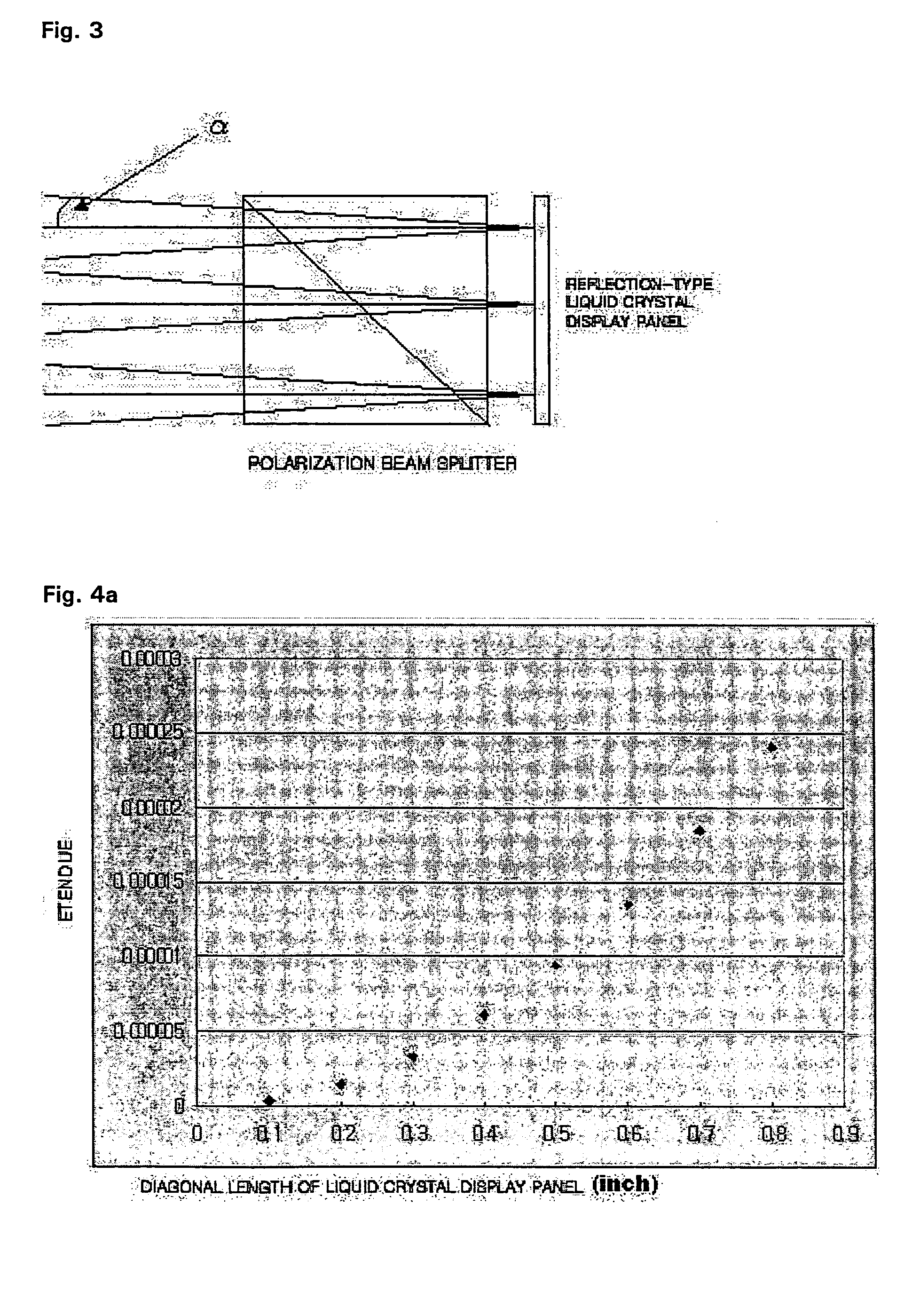
[0033] When the incident angle of the light beam, which is output from an illumination lens of the optical system and input to a polarization beam splitter on the basis of the normal of the boundary face of the polarization beam splitter, is α, the refractive angle of the light b...


PUM


Abstract

Disclosed is a reflection-type micro display projection system having a polarization beam splitter with an optimized structure to increase optical efficiency and improve contrast of images. The reflection-type micro display projection system includes a light source for emitting a light beam, an optical system for transmitting the light beam emitted from the light source, a reflection-type liquid crystal display panel for reflecting the light beam transmitted through the optical system and outputting the light beam as image information, a projection lens for magnifying and projecting the image information, and a screen for displaying an image corresponding to the image information magnified and projected by the projection lens. When the incident angle of the light beam, which is output from an illumination lens of the optical system and input to a polarization beam splitter on the basis of the normal of the boundary face of the polarization beam splitter, is α, the refractive angle of the light beam refracted inside the polarization beam splitter is β, and the refractive index of the polarization beam splitter is n, n×sin β=sin α. The refractive index n is larger than 1.6 and smaller than 2.0.

Description

[0001] This Nonprovisional application claims priority under 35 U.S.C. § 119(a) on Patent Application No. 10-2003-0084945 filed in Korea on Nov. 27, 2003, the entire contents of which are hereby incorporated by reference. BACKGROUND OF THE INVENTION [0002] 1. Field of the Invention [0003] The present invention relates to a reflection-type micro display projection system. More particularly, the invention relates to a reflection-type micro display projection system having a polarization beam splitter with an optimized structure to increase optical efficiency and improve contrast of images. [0004] 2. Description of the Background Art [0005] Recently, display systems have become light and thin while having a large screen. Particularly, a large-screen display system such as a projection TV system becomes important in the display field. [0006]FIG. 1 shows the configuration of a conventional reflection-type micro display projection system. Referring to FIG. 1, the conventional reflection-t...

Claims


Application Information

Patent Timeline
IPC IPC(8): G02B5/30G02F1/13G02F1/1335G03B21/00G03B21/14H04N5/74H04N9/31
CPCH04N9/3197H04N9/3114H04N5/74
Inventor PARK, JONG MYOUNG
Owner LG ELECTRONICS INC
Why Eureka
Try Eureka