
Orthopedic support locating or centering feature and method

a technology of orthopaedic support and feature, applied in the field of improved orthopaedic implants and plates, can solve the problems of numbness, muscle weakness and paralysis, pain, nerve damage, etc., and achieve the effects of improving the quality of li

Active Publication Date: 2007-11-22
WARSAW ORTHOPEDIC INC
View PDF13 Cites 132 Cited by
  • Summary
  • Abstract
  • Description
  • Claims
  • Application Information

AI Technical Summary

Benefits of technology

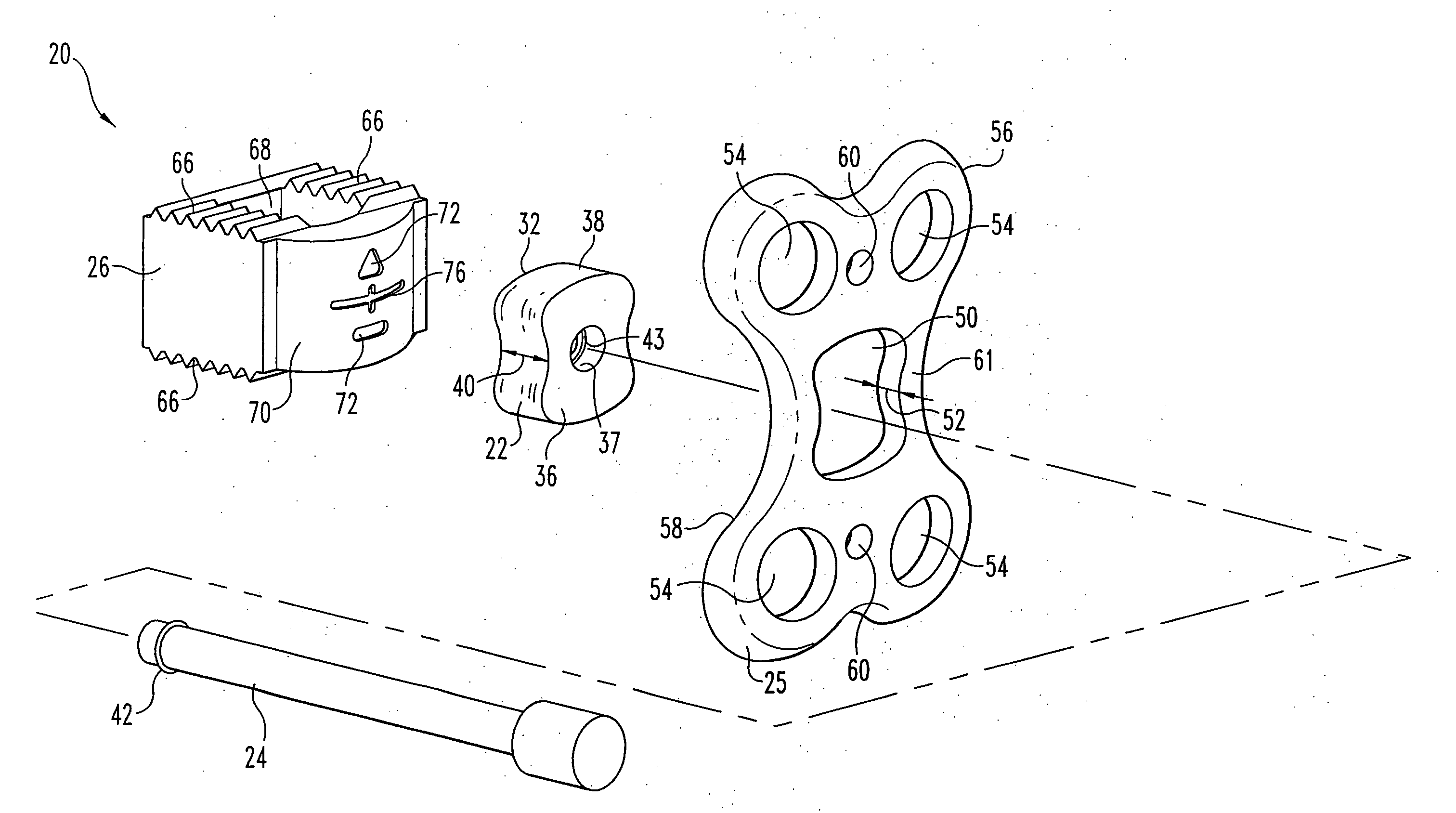
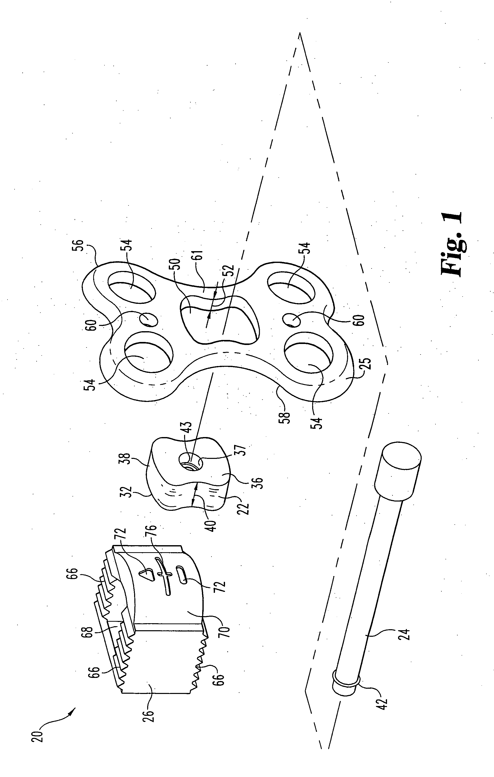
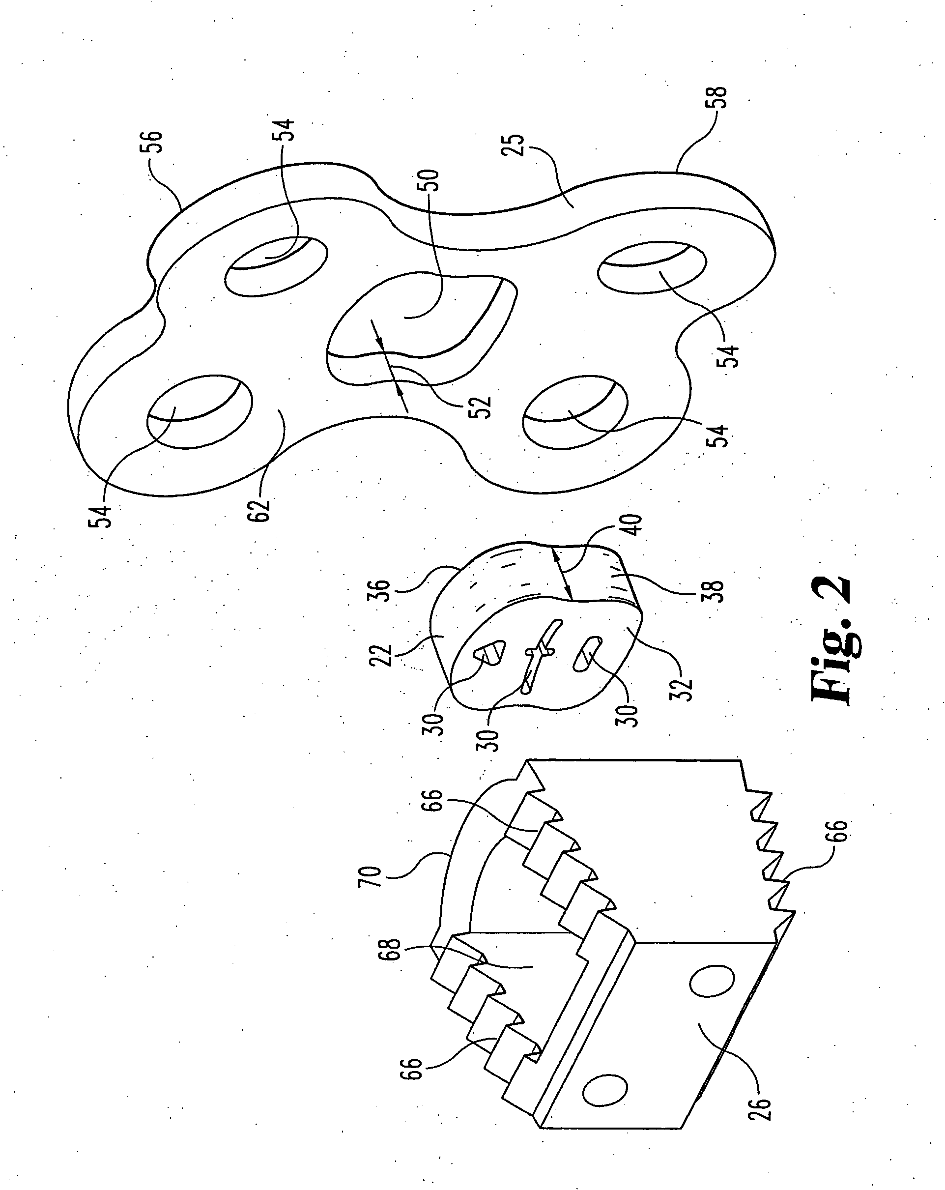
The patent text describes a system for centering a spinal plate across a disc space during spine surgery. The system includes an implant with a centering mark and a centering member with a centering member periphery and thickness. The centering member has at least one protrusion that engages the implant and the spinal plate. The system can be used to position the spinal plate accurately over the implant. The technical effect of this system is to improve the accuracy and precision of spine surgery procedures.

Problems solved by technology

Spinal discs may be displaced or damaged due to trauma, disease, aging, or other factors.
The extruded nucleus pulposus can press on a spinal nerve, which may result in nerve damage, pain, numbness, muscle weakness and paralysis.
Intervertebral discs may also deteriorate due to the normal aging process or disease.
As a disc dehydrates and hardens, the disc space height may be reduced which could lead to instability of the spine, decreased mobility and pain.
In practice, given the vagaries of anatomy, obscuring of the surgical site by tissue or bodily fluids, or for other reasons, it can be difficult to properly position or center a plate over an implant.

Method used


Image

  • Orthopedic support locating or centering feature and method
  • Orthopedic support locating or centering feature and method
  • Orthopedic support locating or centering feature and method

Examples


Embodiment Construction

[0014] For the purposes of promoting an understanding of the principles of the disclosure, reference will now be made to the embodiment illustrated in the drawings and specific language will be used to describe the same. It will nevertheless be understood that no limitation of the scope of the claims is thereby intended, such alterations and further modifications in the illustrated device, and such further applications of the principles of the disclosure as illustrated therein being contemplated as would normally occur to one skilled in the art to which the disclosure relates.

[0015] Referring generally to the figures, there is shown an embodiment of a spinal plate centering system 20. In the illustrated embodiment, system 20 includes centering member 22 and handle 24, which are engageable to spinal plate 25, and implant 26. Generally, as further discussed below, centering member 22 assists in placing plate 25 with respect to implant 26 in a desirable location on bone adjacent impla...


PUM


Abstract

Spinal plate positioning system including a spinal plate, centering member and implant, is used to position and center a spinal plate over an implant in an intervertebral space. Implant may include a centering feature which may engage a surface of centering member or spinal plate to aid in placement of spinal plate.

Description

[0001] This disclosure generally concerns improved orthopedic implants and plates which form a fixation apparatus. In particular, it concerns implants incorporating a feature which aids in the placement of a plate. [0002] Intervertebral discs, located between the endplates of adjacent vertebrae, stabilize the spine, distribute forces between vertebrae and cushion vertebral bodies. A normal intervertebral disc includes a semi-gelatinous component, the nucleus pulposus, which is surrounded and confined by an outer, fibrous ring called the annulus fibrosus. In a healthy, undamaged spine, the annulus fibrosus prevents the nucleus pulposus from protruding outside the disc space. [0003] Spinal discs may be displaced or damaged due to trauma, disease, aging, or other factors. Disruption of the annulus fibrosus allows the nucleus pulposus to protrude into the vertebral canal, a condition commonly referred to as a herniated or ruptured disc. The extruded nucleus pulposus can press on a spina...

Claims


Application Information

Patent Timeline
Patent Type & Authority Applications(United States)
IPC IPC(8): A61F2/44
CPCA61B17/7059A61B2017/0046A61F2230/0065A61F2002/302A61F2002/30904A61F2/4455
Inventor FERGUSON, JOE
Owner WARSAW ORTHOPEDIC INC
Learn More