
Fuel cell device with a textured electrolyte sheet and a method of making such sheet

Active Publication Date: 2007-11-29
CORNING INC
View PDF16 Cites 14 Cited by
  • Summary
  • Abstract
  • Description
  • Claims
  • Application Information

AI Technical Summary

Benefits of technology

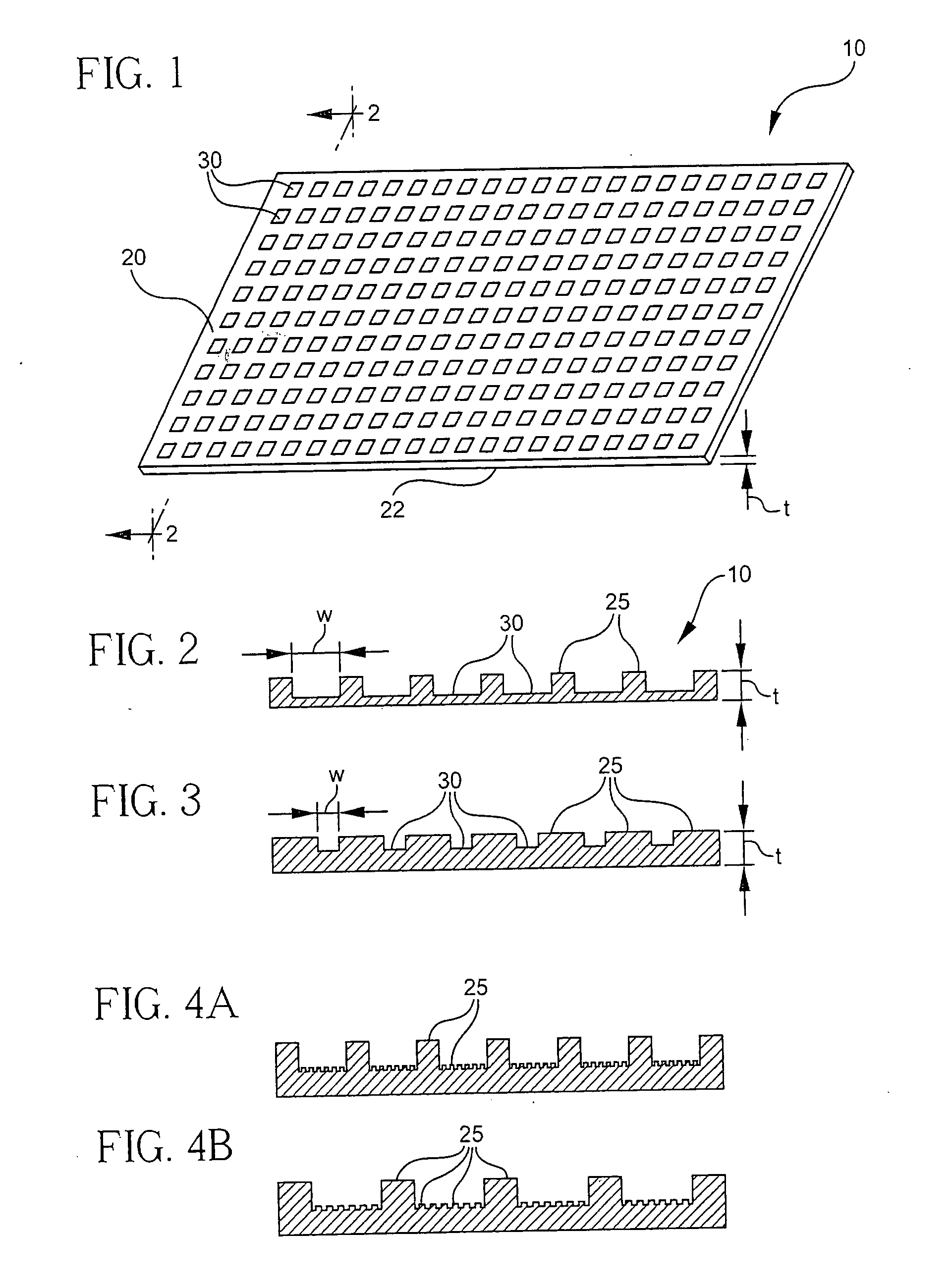
[0012] According to one aspect of the present invention the fuel cell device includes an electrolyte sheet. The electrolyte sheet has a substantially non-porous body of a varied thickness, a relatively smooth surface and a more textured surface with multiple indentations therein, wherein the thickest part

Problems solved by technology

This patent does not disclose solid oxide fuel cells, does not describe the thickness of the electrolyte, nor the dimensions of the features on the textured surfaces.
However, reduction in electrolyte thickness results in physical weakening of the electrolyte.
For example, a ceramic electrolyte sheet having a thickness below 10 micrometers often breaks during handling or processing making process yields relatively low.
In addition, a defect in an electrolyte sheet may necessitate a replacement of entire electrolyte structure.

Method used


Image

  • Fuel cell device with a textured electrolyte sheet and a method of making such sheet
  • Fuel cell device with a textured electrolyte sheet and a method of making such sheet
  • Fuel cell device with a textured electrolyte sheet and a method of making such sheet

Examples


example 1

[0098]FIG. 11A illustrates one example of the electrolyte sheet of the present invention. FIG. 11B illustrates the cross-sectional view of the electrolyte sheet of FIG. 11A. The electrolyte sheet 10 of this example has two textured surfaces 20, 22. This electrolyte sheet was made as follows: [0099] i. In a filtered air “clean” environment, Teflon® coated cloth (150 micron-Ultra Premium Grade PTFE coated fiberglass fabric, available from CS Hyde Co., Lake Villa Ill., USA) is smoothed out on a glass plate and then attached to the glass plate with tape. The Teflon® coated cloth has an existing micro texture (weave). [0100] ii. A slip of zirconia-3 mole % yttria powder is coated on the Teflon® coated cloth using a tape casting “doctor” blade with a 50 micron gap and a 15 cm width, forming a green sheet. [0101] iii. The micro-textured green sheet (i.e. the green sheet with the size of features 25 between 0.5 and 50 microns) was dried for ½ hour at room temperature under a plastic cover t...

example 2

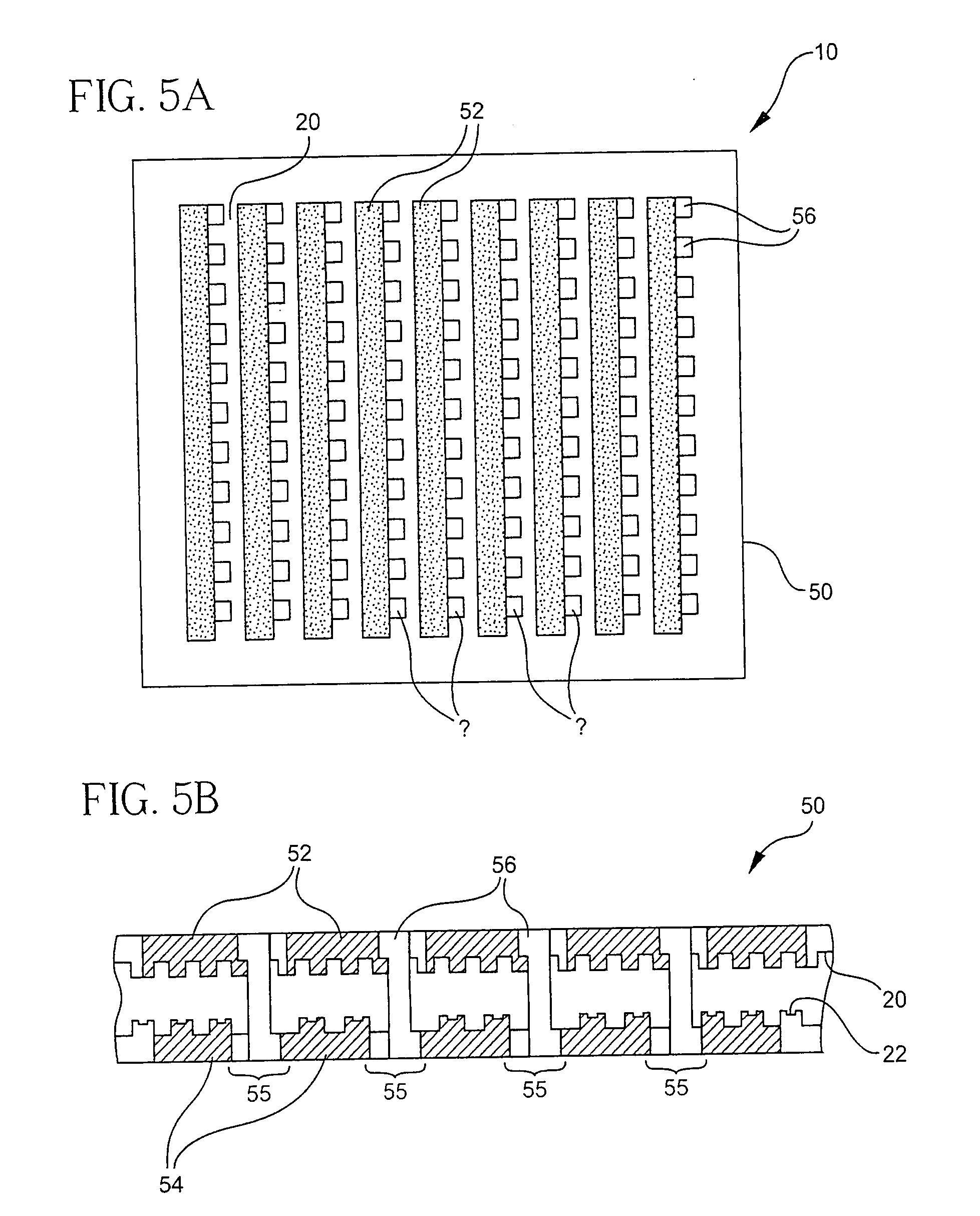
[0108] Applicants also discovered that it is desirable to modulate the electrolyte thickness in a patterned fashion in order to improve its net mechanical properties. First consider the case of an electrolyte of uniform thickness. If the space between electrode strips (i.e., via galleries 55) has less printed material (to accommodate vias and / or via pads) the via gallery will be comparatively less “stiff” then the electrode regions. On flexure of the device, the via gallery regions will be subject to stress concentration because they are relatively more flexible than the electrode regions and will have a relatively short radius of curvature. In this case, because we wish to avoid concentrating stress in the regions between the electrodes which contain the vias (i.e., through holes), a more uniform flexure is desired throughout the electrolyte sheet. Therefore, it will be advantageous to provide more thickness in the via gallery regions, which will provide more uniform flexure of the...

example 3

[0110]FIG. 14 illustrates another example of the electrolyte sheet 10 with a textured surface 20. Surface 20 includes a plurality of linear indentations or grooves. These features are 3 micrometers wide and 3 micrometers deep and separated by 3 micrometers. The non-grooved portions of the electrolyte sheet 10 are 15 micrometers thick. The grooves reduce the average electrolyte thickness by 1.5 micrometers (10%) and increase the surface area by a factor of 2 (100%) in the textured region.

[0111] A similar plurality of grooves with 1 micron separations, vertical walls, 1 micrometer wide and 6 micrometers deep will have an aspect ratio of 6:1 and thus reduce the average electrolyte sheet thickness by 3.5 micrometers (20%) while increasing the surface area by a factor of seven.

[0112] As another variation of this example, an array of grooves 3 micrometers wide and 5 micrometers deep with wall angles of 70 degrees reduces the thickness of the electrolyte sheet by 2.5 micrometer (about 17...


PUM

PropertyMeasurementUnit
Temperatureaaaaaaaaaa
Lengthaaaaaaaaaa
Lengthaaaaaaaaaa

Abstract

According to one aspect of the present invention the fuel cell device includes an electrolyte sheet. The electrolyte sheet has a substantially non-porous body of a varied thickness, a relatively smooth surface and a more textured surface with multiple indentations therein, wherein the thickest part of the electrolyte sheet is at least 0.5 micrometers greater than the thinnest part of said electrolyte sheet. The side of the electrolyte sheet with a relatively smooth surface is subjected to the predominately tensile force and the other, more textured surface subjected to predominately compressive force. According to one embodiment, the fuel cell also includes one cathode disposed on the more textured side of said electrolyte sheet at least at least one anode disposed opposite the cathode on the relatively smooth side of aid electrolyte sheet. According to one embodiment, the relatively smooth side of the electrolyte sheet is the fuel facing side and the more textured side is the air-facing side

Description

CROSS-REFERENCE TO RELATED APPLICATIONS [0001] This is a continuation-in-part of U.S. patent application Ser. No. 10 / 611,507 filed on Jun. 30, 2003, the content of which is relied upon and incorporated herein by reference in its entirety, and the benefit of priority under 35 U.S.C. § 120 is hereby claimed.BACKGROUND OF THE INVENTION [0002] 1. Field of the Invention [0003] The present invention relates generally to inorganic electrolyte sheets suitable for use in fuel cells and, more particularly to textured electrolyte sheets suitable for use in solid oxide fuel cells. [0004] 2. Technical Background [0005] U.S. Pat. No. 4,135,040 describes the use of textured electrolyte to increase ion-conductive surface area. The patent specifies that this electrolyte is suitable for use in sodium-sulfur, sodium-halogen, lithium anode type cells and solid state cells. These types of galvanic “battery” cells utilize solid state electrolytes which conduct positive ions, such as sodium or lithium, wh...

Claims


Application Information

Patent Timeline
IPC IPC(8): C04B35/64H01MH01M8/10H01M8/12H01M8/24
CPCC04B35/486H01M8/1246C04B2235/3224C04B2235/3225C04B2235/3229C04B2235/3232C04B2235/3251C04B2235/3256C04B2235/3258C04B2235/3286C04B2235/3293C04B2235/602C04B2235/945H01M8/1253H01M2300/0077Y02E60/521Y02E60/525C04B35/64Y02E60/50Y02P70/50
Inventor BADDING, MICHAEL E.BROWN, JACQUELINE L.GARNER, SEAN M.KETCHAM, THOMAS D.ST. JULIEN, DELL J.
Owner CORNING INC
Learn More