Device And Method For Conditioning Nuclear Fuel Assemblies With Double Confinement Barrier

a technology of confinement barrier and nuclear fuel, which is applied in the direction of electrodes and associated parts, reactor fuel elements, instruments, etc., can solve the problems of time and cost, more restrictive techniques, and inability to condition under water, etc., and achieve the effect of facilitating existing procedures

Inactive Publication Date: 2007-11-29
COGEMA LOGISTICS
View PDF6 Cites 9 Cited by
  • Summary
  • Abstract
  • Description
  • Claims
  • Application Information

AI Technical Summary

Benefits of technology

[0012] The invention also relates to a double receptacle drainage process, and a process for conditioning radioactive equipment using this drainage process. These processes make it possible to package equipment under water. Advantageously, two leak tight metallic receptacles are used so as to achieve double confinement of the radioactive material without complicating the necessary equipment due to the presence of a dry containment, each step possibly being performed under water.
[0013] Another aspect of this invention is a leak tight metallic inner receptacle, the shape of which facilitates existing procedures, particularly concerning draining and therefore sealing the outer receptacle in which it will subsequently be conditioned. Consequently the inner receptacle, composed of a conventional container with a non removable bottom, is also equipped with a duct that passes through the bottom and leaves a free passage when the receptacle is sealed. This passage enables the introduction of gas and / or suction into the receptacle surrounding it.

Problems solved by technology

The disadvantage of this method is its complexity, and consequently the time and cost, of the containment and also the tools and manipulation arms.
However, this technique is more restrictive because part of it has to be done while totally immersed in more than ten metres of water.
In this case, conditioning under water has not been possible up to now, particularly due to problems with drainage of the second confinement containment.

Method used


Image

  • Device And Method For Conditioning Nuclear Fuel Assemblies With Double Confinement Barrier
  • Device And Method For Conditioning Nuclear Fuel Assemblies With Double Confinement Barrier
  • Device And Method For Conditioning Nuclear Fuel Assemblies With Double Confinement Barrier

Examples


Embodiment Construction

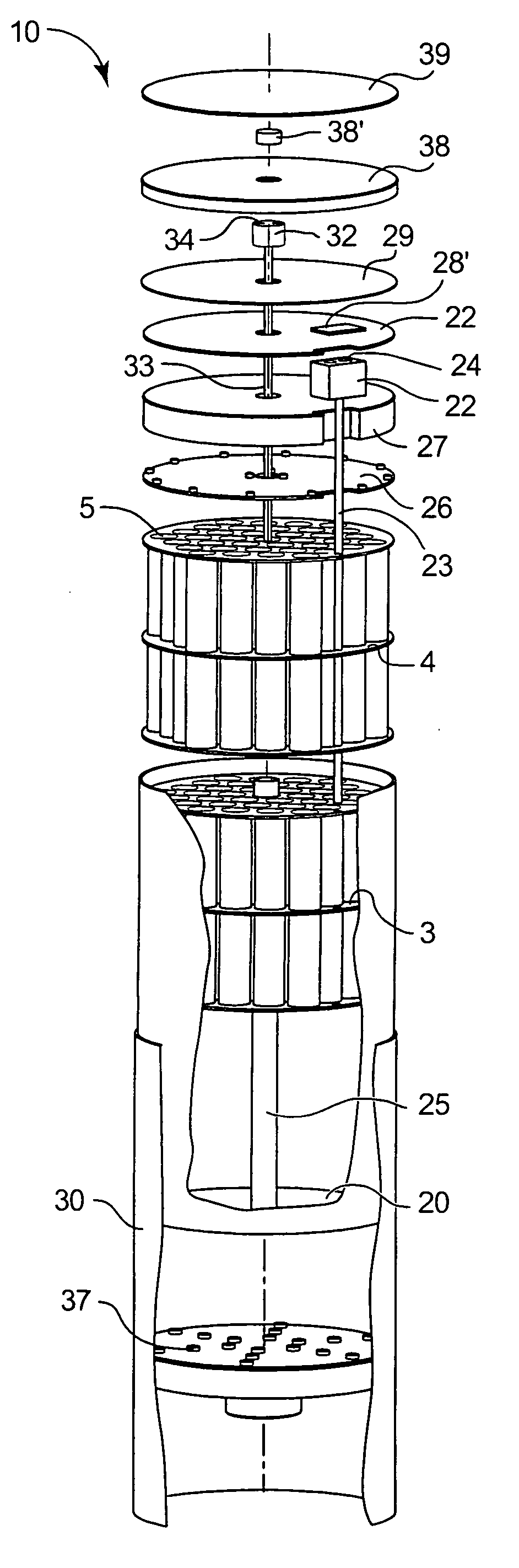
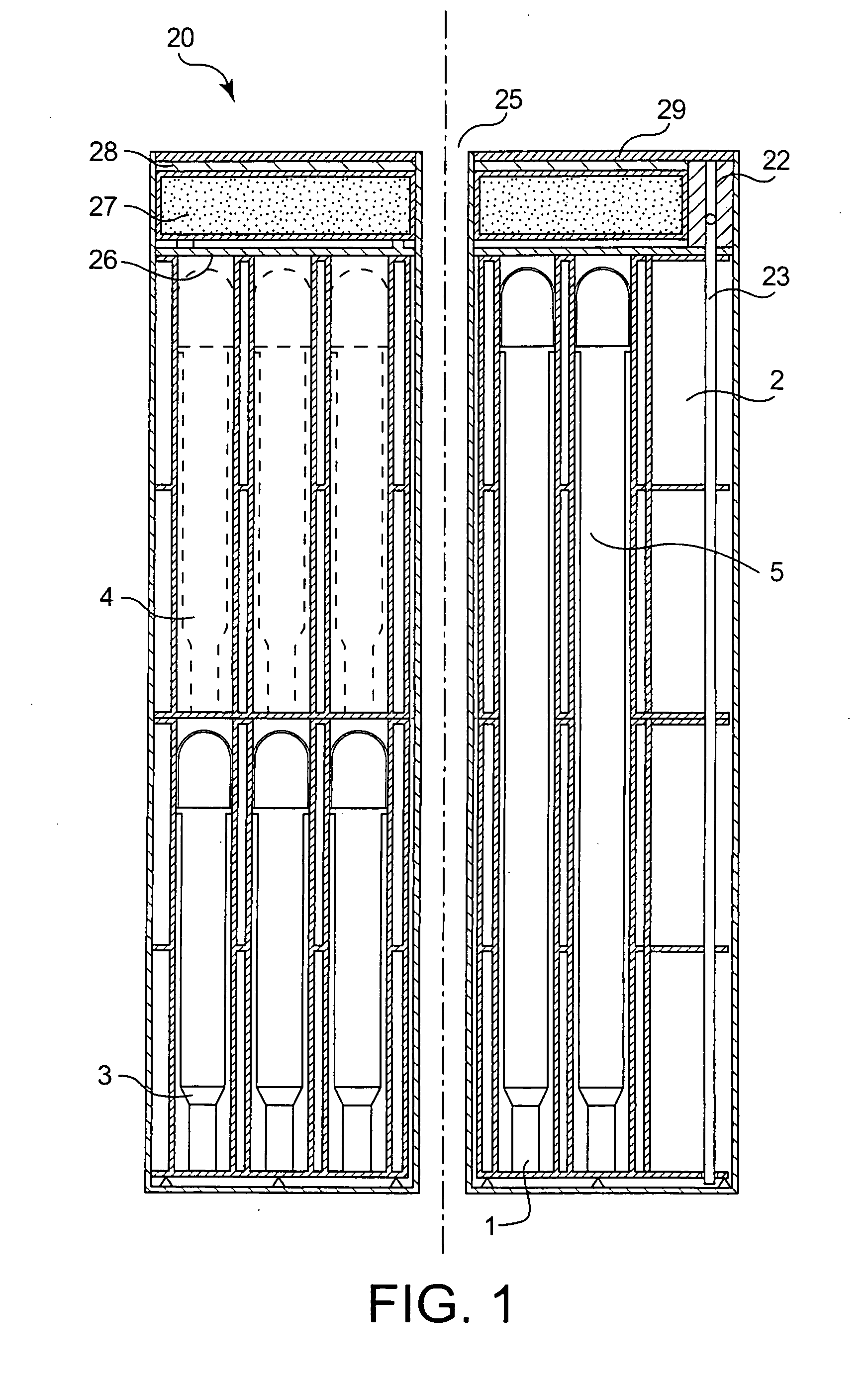
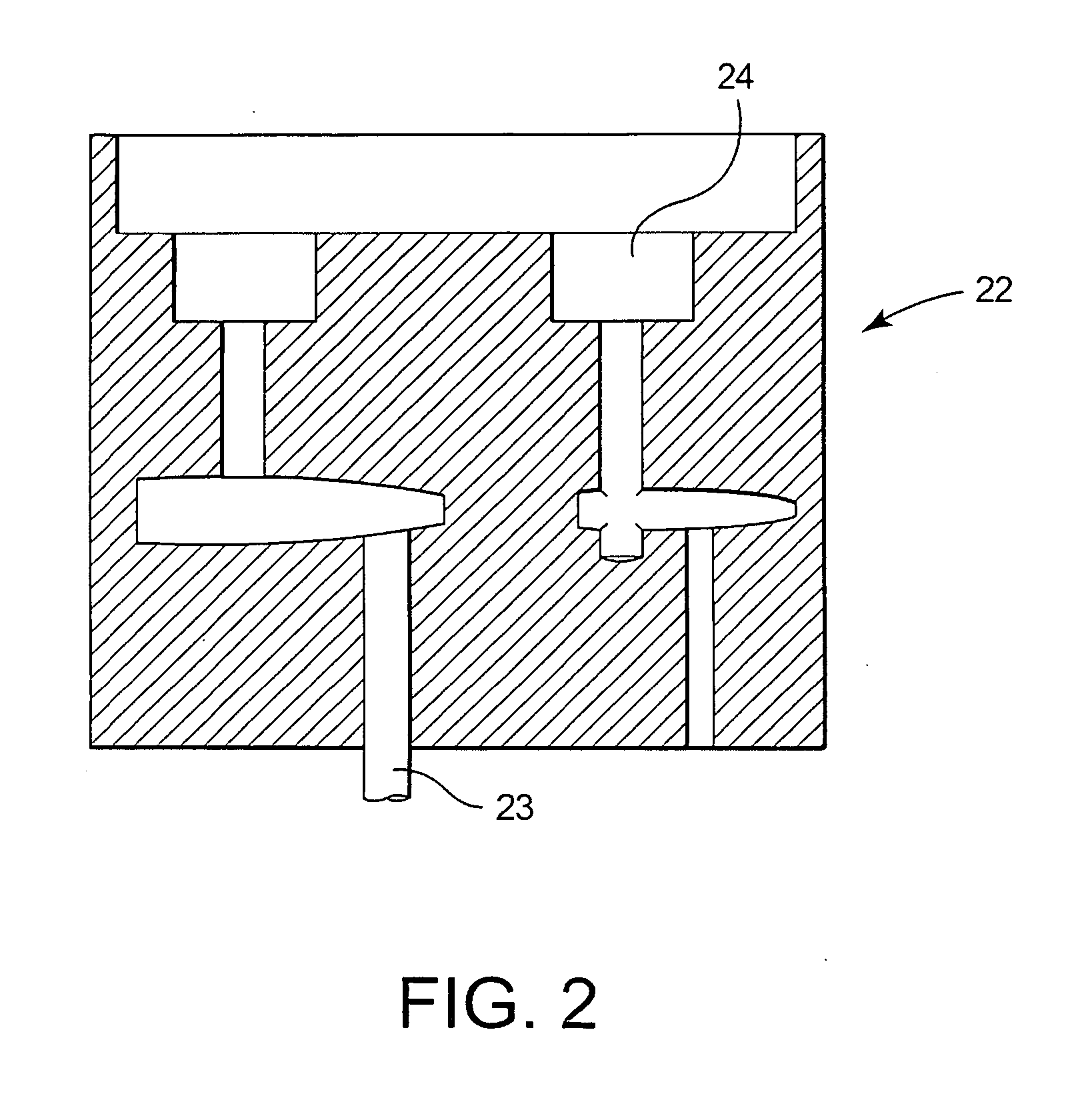
[0022]FIG. 1 shows a metallic confinement receptacle (20), formed from a cylindrical receptacle with sidewalls and a loading opening, closed at its lower end by non-removable bottom. A duct (25) with a circular section also passes through the centreline of the metallic receptacle (20): therefore, the duct has walls along its length but remains open at both its ends. The walls of the receptacle, in other words the sidewalls and the walls of the duct, resist radioactivity but do not necessarily provide radiation shielding. It is obvious that these different forms and arrangements are preferred but not essential examples; for example a receptacle with a parallelepiped shaped section, a side duct and / or a duct with any other shape are other possibilities.

[0023] Before loading irradiated fuel assemblies (1), the confinement receptacle (20) is placed in the pool of the nuclear power station. In the context of safety measures and particularly processes according to the invention, the rece...


PUM


Abstract

Transport and storage of nuclear fuel assemblies may require double confinement depending on the circumstances. A device and a method are described to perform this double conditioning without the need of a hot containment, and in which the loading and pre-positioning steps can take place in a pool.
The device (10) includes a metallic inner leak tight conditioning receptacle (20) and a metallic outer leak tight receptacle (30). When the inner receptacle (20) is located in the outer receptacle (30), a passage (15, 25) remains free between the two receptacles, from the open end to the bottom of the outer receptacle. The outer receptacle (30) can be drained through this passage, particularly by a dip tube (33).

Description

TECHNICAL FIELD [0001] This invention relates to conditioning of nuclear fuel assemblies and more particularly to devices enabling double confinement of assemblies, and the conditioning procedure in receptacles before transport or storage, if any. BACKGROUND ART [0002] Nuclear fuel assemblies require particular procedures for their use, transport and even for disposal as waste. Thus, irradiated nuclear fuel assemblies from nuclear power stations have to be stored after use. Nuclear power plants are provided with a pool in which these assemblies are stored, but this storage is temporary and the nuclear fuel assemblies then have to be evacuated to safe so-called “final” or “interim” storage sites, and in particular including leak tight metallic confinements protected by concrete storage modules. [0003] To transport them to their destination, leak tight confinements containing nuclear fuel assemblies need to be put into place in “temporary” radiation shielding receptacles. Therefore sa...

Claims


Application Information

Patent Timeline
Patent Type & Authority Applications(United States)
IPC IPC(8): G21C19/07G21F5/005G21F5/008G21F5/06
CPCG21F5/005G21F5/008G21F5/06G21Y2004/40G21Y2002/301G21Y2002/304G21Y2004/30G21Y2002/202G21F5/12
Inventor CHIOCCA, RENE
Owner COGEMA LOGISTICS
Why Eureka
Try Eureka