Apparatus and methods for verifying an acceptable splice termination

a technology of splice termination and apparatus, applied in the field of apparatus and methods for verifying an acceptable splice termination, can solve the problems of difficult even for a highly-trained and experienced operator to assess the performance of the fiber optic connector, and significant time and expense still required to mount the fiber optic connector

Active Publication Date: 2007-11-29
CORNING OPTICAL COMM LLC
View PDF31 Cites 32 Cited by
  • Summary
  • Abstract
  • Description
  • Claims
  • Application Information

AI Technical Summary

Problems solved by technology

Regardless, significant time and expense is still required to mount the fiber optic connector onto the field optical fiber, remove the cable assembly from the installation tool, conduct the continuity test and, in the event of an unacceptable splice termination, repeat the entire process.
In particular, it may be difficult even for a highly-trained and experienced operator to assess whether the change in the amount of glow emanating from the termination area is substantial enough to indicate an acceptable splice termination.
These misguided efforts of the untrained or inexperienced operator typically cause damage to the fiber optic connector or to the field optical fiber, or result in optical performance that is less than that which would have been achieved had the operator accepted the first termination, even though the glow was not completely diminished and the nuisance glow persisted.

Method used


Image

  • Apparatus and methods for verifying an acceptable splice termination
  • Apparatus and methods for verifying an acceptable splice termination
  • Apparatus and methods for verifying an acceptable splice termination

Examples


Embodiment Construction

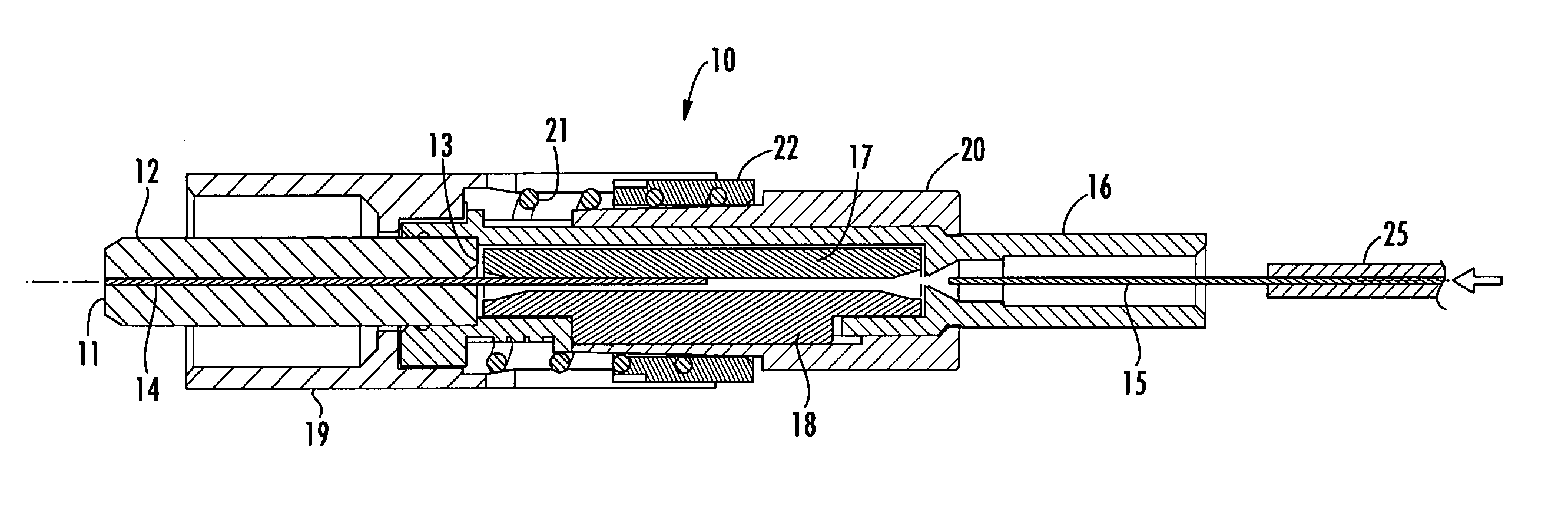
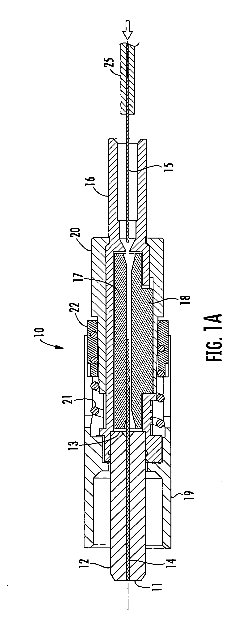
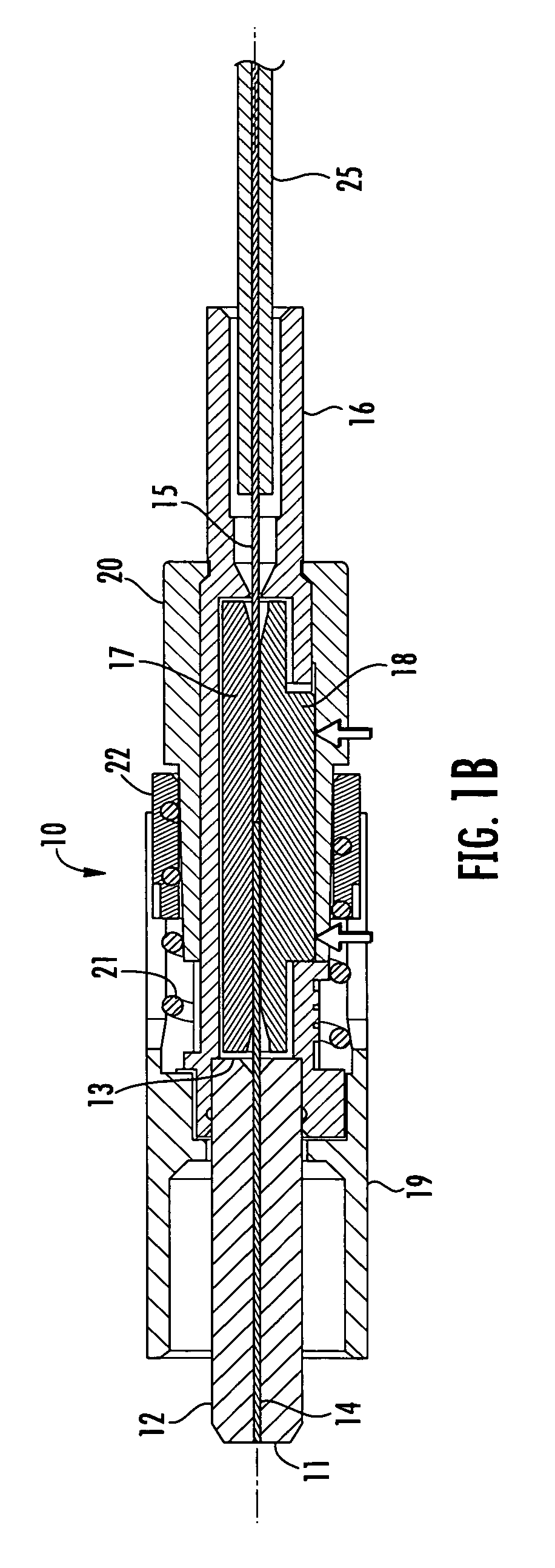
[0021] Reference will now be made in greater detail to various exemplary embodiments of the invention, preferred embodiments of which are illustrated in the accompanying drawings. Whenever possible, the same reference numerals will be used throughout the drawings to refer to the same or similar parts. A single fiber field-installable mechanical splice connector operable for terminating a field optical fiber to the connector is shown herein for use with the various embodiments of the invention merely for purposes of convenience. It should be understood, however, that the apparatus and methods for verifying an acceptable splice termination disclosed herein may be applied to any optical coupling between any number of optical fibers, such as, but not limited to, any splice termination between adjoining optical fibers wherein light energy can be transmitted along at least one of the optical fibers and the light energy can be detected, collected and measured in the immediate vicinity of t...


PUM


Abstract

Apparatus and methods for verifying an acceptable splice termination include propagating light energy into the stub optical fiber of a fiber optic connector, detecting and collecting the amount of optical power emanating from the stub optical fiber at a termination area of the connector, converting the optical power to an electrical signal proportional to the amount of collected optical power, and displaying the electrical signal on a feedback monitor, such as an optical power meter, an LCD bar graph, or an LED. An initial (i.e., reference) value is obtained with the field optical fiber not in physical contact with the stub optical fiber. A final (i.e., terminated) value is obtained with the field optical fiber in physical contact with the stub optical fiber and terminated to the connector. The final value is compared to the initial value to determine whether the change (i.e., difference) is sufficient. Alternatively, the final value is compared to a predetermined limit or threshold.

Description

BACKGROUND OF THE INVENTION [0001] 1. Field of the Invention [0002] The present invention relates generally to apparatus and methods for determining whether the continuity of the optical coupling between optical fibers is acceptable, and more particularly, to apparatus and methods for verifying an acceptable splice termination between a field optical fiber and a stub optical fiber in a fiber optic splice connector. [0003] 2. Technical Background [0004] Optical fibers are useful in a wide variety of applications, including the telecommunications industry in which optical fibers are employed for voice, data and video transmission. Due, at least in part, to the extremely wide bandwidth and the low noise operation provided by optical fibers, the variety of applications in which optical fibers are being used is continuing to increase. For example, optical fibers no longer serve merely as a medium for long distance signal transmission, but are being increasingly routed directly to the hom...

Claims


Application Information

Patent Timeline
Patent Type & Authority Applications(United States)
IPC IPC(8): G02B6/00
CPCG02B6/3802G02B6/3806G02B6/3846
Inventor BILLMAN, BRADLEYMEEK, DAVIDRAKER, JOSHUASEMMLER, SCOTT
Owner CORNING OPTICAL COMM LLC
Why Eureka
Try Eureka