
Vehicles and Trailers Incorporating Moveable Load Carrying Platforms

a technology of moving platforms and trailers, which is applied in the direction of loading/unloading vehicles, transportation items, braking systems, etc., can solve the problems of increasing labor intensity, time-consuming and labor-intensive, and no satisfactory way of transferring cargo from the lift onto the upper cargo carrying surface, so as to avoid any significant reduction in the internal width of the vehicle available, the effect of simple and robust mechanism

Inactive Publication Date: 2007-11-29
MIDDLEGATE MARKETING LTD
View PDF7 Cites 3 Cited by
  • Summary
  • Abstract
  • Description
  • Claims
  • Application Information

AI Technical Summary

Benefits of technology

[0016] The, or each, well platform may support projections received within vertical guide tracks fitted to the well walls. The guide tracks ensure the appropriate positioning of the platform within the well. In addition, means may be provided for obstructing upper ends of the guide tracks so that, after a platform has been raised to an elevated position, the guide tracks may be obstructed so that the platform will be prevented from moving downwards from the elevated position. Thus an inherently safe mechanical structure is provided which will protect against accidental lowering of the platforms in the event for example of hydraulic failure.
[0018] Thus a simple and robust mechanism is provided which enables payload to be lifted up and moved over the well section. This is achieved by using low-profile supports in the sidewalls, avoiding any significant reduction in the internal width of the vehicle available for receiving payload.

Problems solved by technology

The trailer of U.S. Pat. No. 5,092,721 is disadvantageous in that there is no satisfactory way of transferring cargo from the lift onto the upper cargo carrying surface.
Furthermore, transferring the cargo manually is likely to be time consuming and labour intensive
However, each of the mechanisms described in this document is suitable only for loading pallets using a forklift truck, not for carrying roll cages which are often used to carry cargo in trailers, nor for loading pallets using a manually operated pallet-barrow.

Method used


Image

  • Vehicles and Trailers Incorporating Moveable Load Carrying Platforms
  • Vehicles and Trailers Incorporating Moveable Load Carrying Platforms
  • Vehicles and Trailers Incorporating Moveable Load Carrying Platforms

Examples


Embodiment Construction

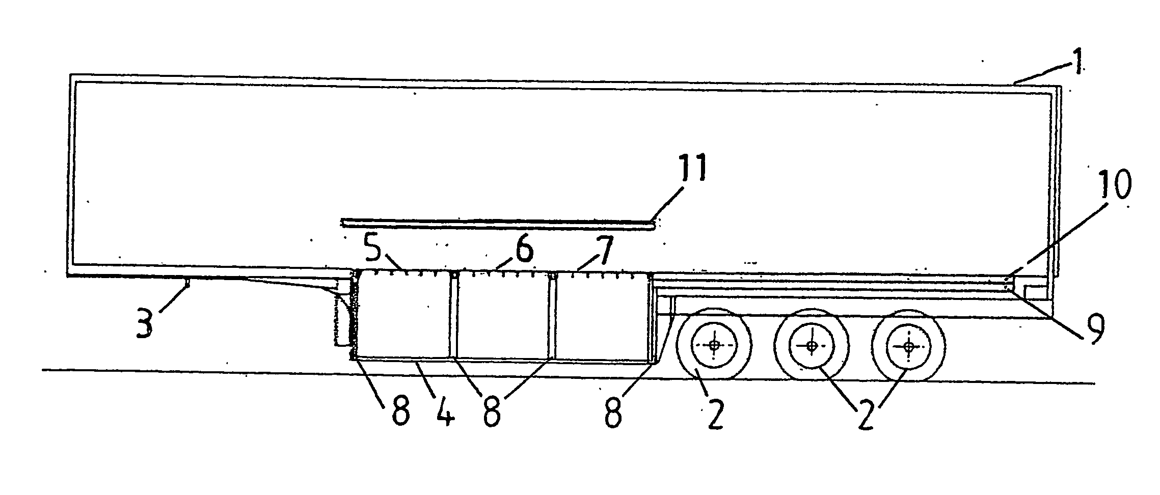
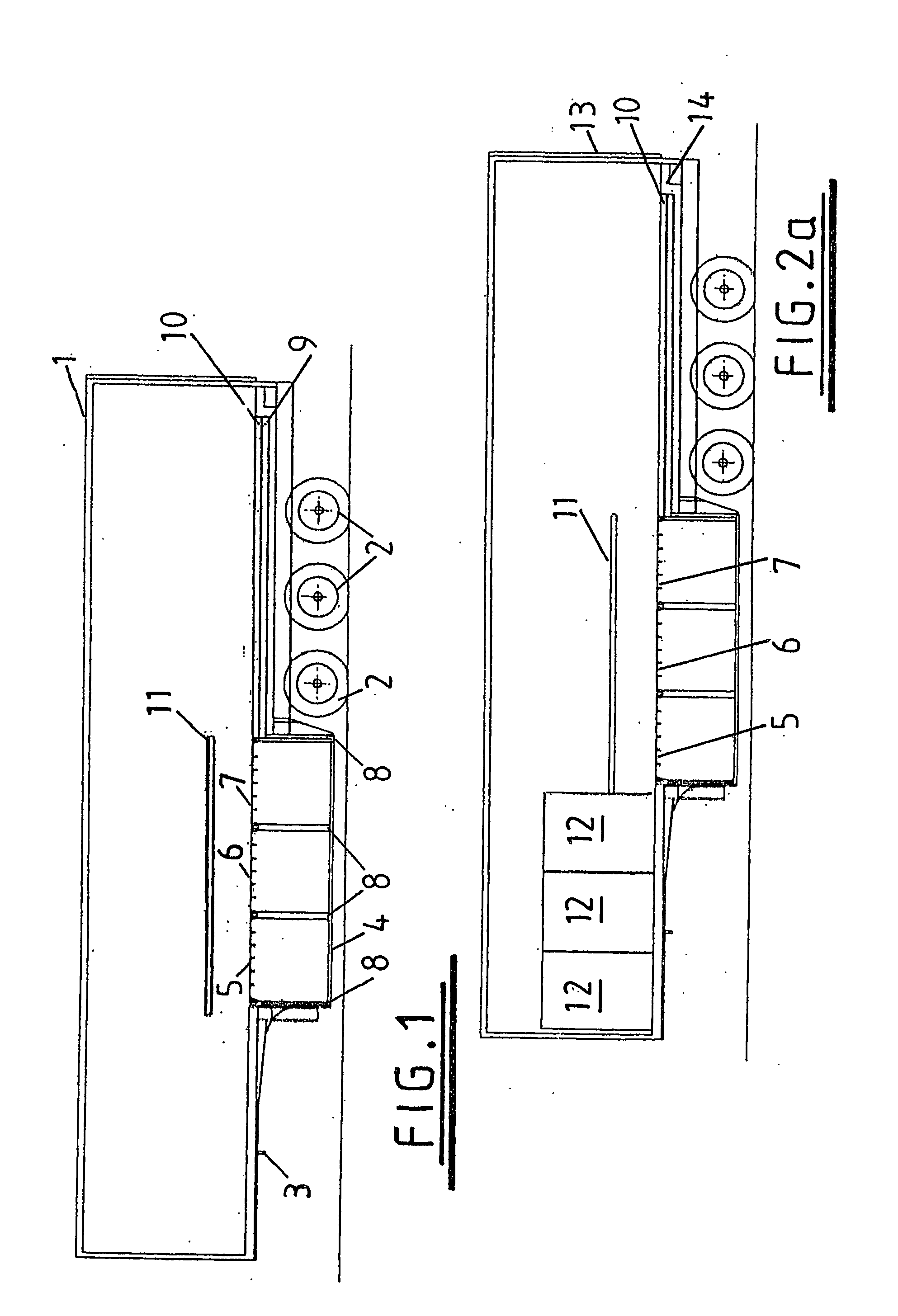
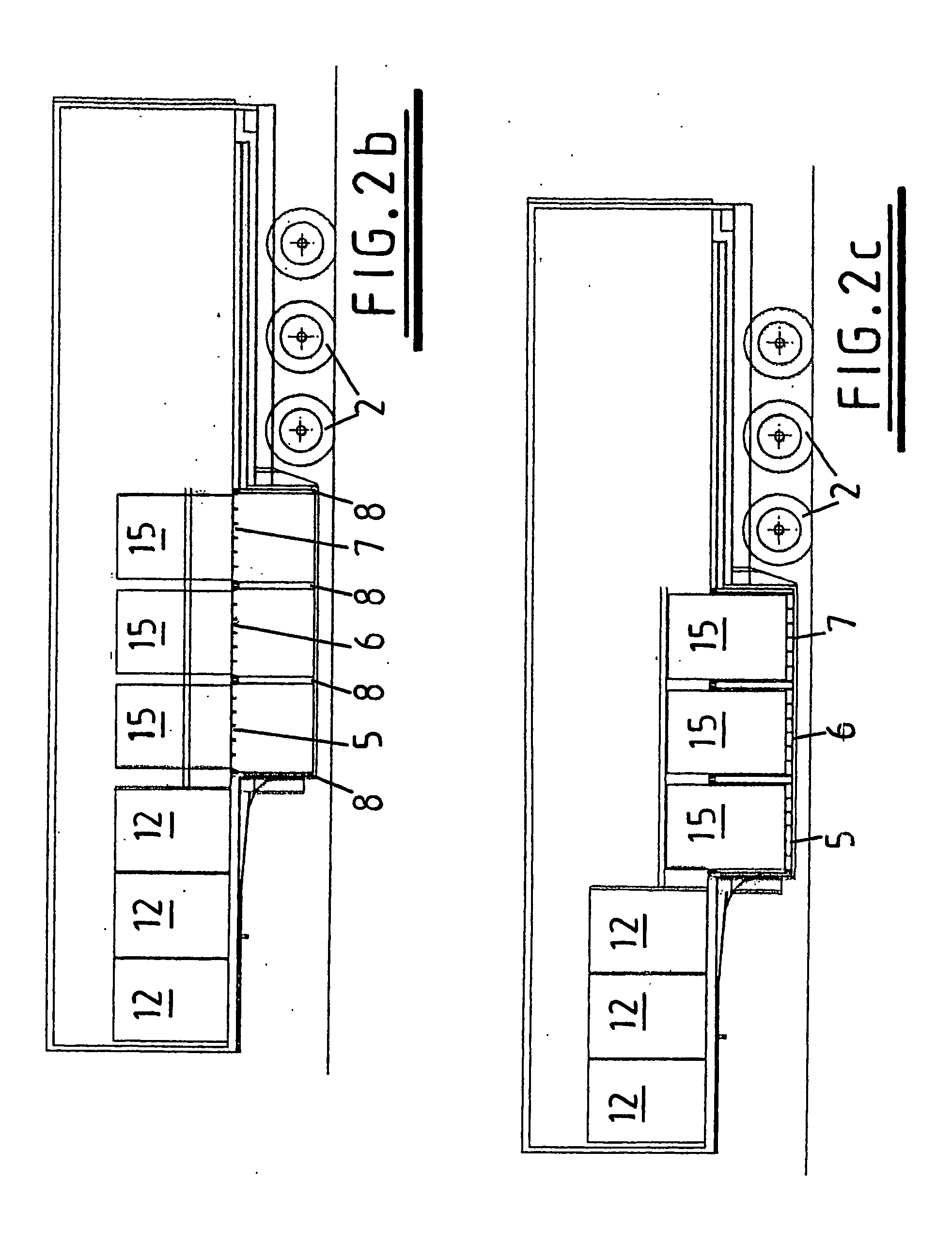
[0049]FIG. 1 shows a trailer 1 having three rear axles supporting wheels 2 and a front hitch 3 (which may also be referred to as a king pin, and which typically is received in the fifth wheel of the tractor unit). It can be seen that a central part of the floor of the trailer between the wheels 2 and the front hitch 3 is lower than front and rear floor sections, so as to allow additional cargo to be carried in the lower part of the trailer which is hereinafter referred to as a well 4. It can be seen that, in this example, the well is provided with three vertically moveable platforms 5, 6 and 7 which can be raised and lowered by the action of hydraulic rams 8. In other embodiments, the well may be provided with a different number of platforms, and the well-platform lifting may be achieved by other means. For example, and as will be described later, in certain embodiments the well may have a single platform, lifted by a suitably actuated scissor jack arrangement.

[0050] In this first ...


PUM


Abstract

A trailer is described, defining a floor extending from a first end, and comprising at least one first displaceable platform onto which goods can be loaded from the first end of the trailer. The first platform is supported such that it can be elevated when loaded and advanced away from the first end of the trailer when loaded. The first platform is preferably rolled forwards onto support tracks provided on the sidewalls of the trailer. The trailer may also include a load-carrying well with its own moveable cargo platform or platforms, and the first platform is loaded and moved up and over the well, thereby increasing the capacity of the trailer. Corresponding cargo-carrying vehicles, and loading methods are described and claimed.

Description

FIELD OF THE INVENTION [0001] The present invention relates to trailers and vehicles, and in particular, although not exclusively, to trailers and vehicles incorporating a load-carrying well. BACKGROUND TO THE INVENTION [0002] Conventional trailers provide an enclosable space into which cargo can be loaded for carriage. Such trailers are usually provided with a rectangular frame, and a number of solid panels attached to the rectangular frame. Such trailers are mounted on a chassis comprising suitable running gear, to allow connection of the trailer to a tractor unit for haulage purposes. [0003] In order to maximise the carrying capacity of the known trailer, it is known to lower the base of the trailer between the rear axle and the front hitch of the trailer so as to form a well. Such a modification generally allows additional goods to be stacked within the trailer on top of one another. [0004] One trailer having such a well is described in U.S. Pat. No. 5,092,721. In the trailer of...

Claims


Application Information

Patent Timeline
Patent Type & Authority Applications(United States)
IPC IPC(8): B60P3/077B60P1/02B60P1/38
CPCB60P1/38B60P1/02B60P1/00
Inventor DIBDIN, T. PETERDAWES, PAULINE
Owner MIDDLEGATE MARKETING LTD
Learn More