Mixer having frequency selection function

a frequency selection and function technology, applied in the field of mixers, can solve the problems of insufficient improvement of frequency selection characteristics, failure to achieve the effect of enhancing the frequency selection function, and the problem of conventional mixers as described abov

Inactive Publication Date: 2007-11-29
PANASONIC CORP
View PDF11 Cites 27 Cited by
  • Summary
  • Abstract
  • Description
  • Claims
  • Application Information

AI Technical Summary

Benefits of technology

[0012] Therefore, an object of the present invention is to provide a mixer which has an enhanced frequency selection function and represents a characteristic of a high-order IIR filter in which no pass loss occurs in a signal passband, without using an operation control signal having a frequency higher than a sampling frequency.

Problems solved by technology

However, the conventional mixer as described above has a problem as descried below.
That is, in the conventional arts (see FIG. 13) disclosed in US Patent Application Publication No. 2003 / 0040294 and Japanese Laid-Open Patent Publication No. 2004-289793 (corresponding to US Patent Application Publication No. 2003 / 080888), the order of the IIR filter is one, so that frequency selection characteristic is not sufficiently improved.
As shown in FIG. 16, in the conventional art disclosed in US Patent Application Publication No. 2005 / 0104654, a pass loss occurs in a signal passband each time an order is increased, and the increase of the order leads to accumulation of the pass loss.
However, it is complicated to set filter characteristic so as to prevent an output of the IIR filter from interfering with an input thereof, resulting in the designing being difficult.
There is a problem that, when a delay circuit is used, variations in delay time occur.
In particular, since a plurality of operation control signals are required so as to increase an order of an IIR filter, it is substantially difficult to compensate the variations in delay times of the plurality of operation control signals.
Thus, when the operation control signal having a frequency higher than a sampling frequency is used, the reference CLK generation circuit is complicated and consumption of current is increased, and further consumption of power in the logic circuit is increased.
Further, even a simple combination of the conventional arts described above cannot prevent increase in consumption of current caused by pass loss occurring due to the order increase and by the use of an operation control signal having a frequency higher than a sampling frequency.

Method used


Image

  • Mixer having frequency selection function
  • Mixer having frequency selection function
  • Mixer having frequency selection function

Examples


first embodiment

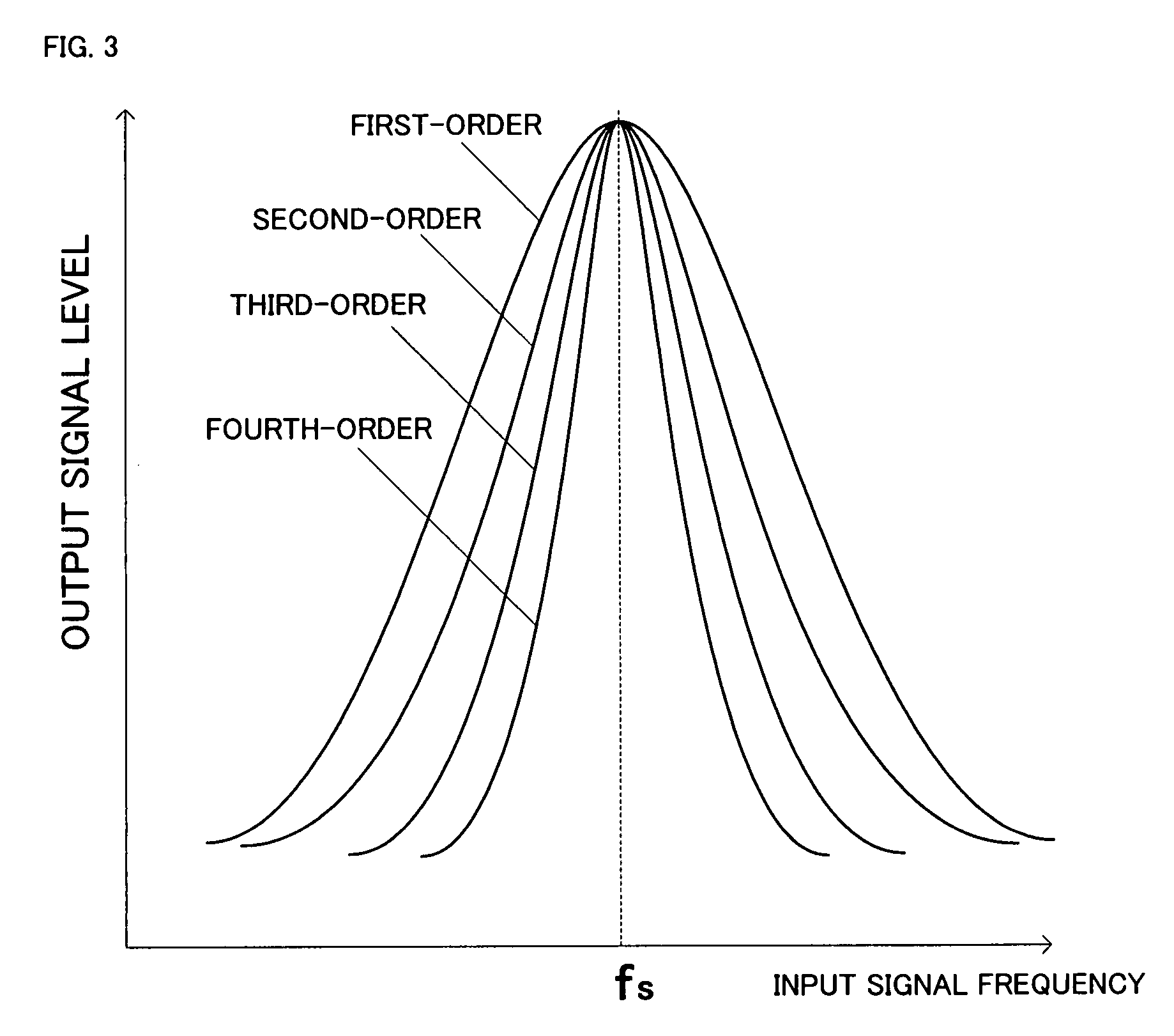
[0040] According to the present invention, a mixer having an enhanced frequency selection characteristic is realized, without increasing a frequency of an operation control signal, by operating a high-order IIR filter in accordance with an operation time for a circuit to which the charge sampling technique is applied. Hereinafter, embodiments of the mixer of the present invention will be described with reference to the drawings. The components common in each FIG. are denoted by the same reference numerals, and a repeated description is not given.

first example

(1) First Example

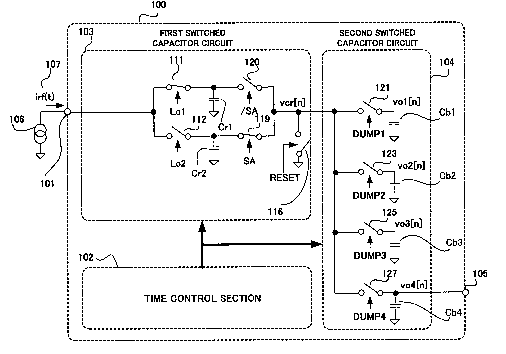
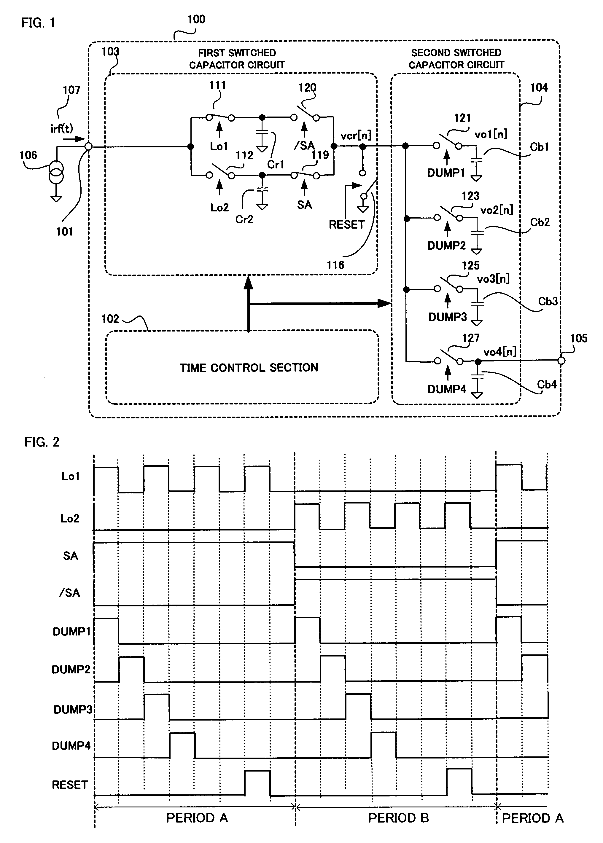
[0041]FIG. 1 is a diagram illustrating a structure of a mixer 100 having a frequency selection function of a first example according to the first embodiment of the present invention. As shown in FIG. 1, the mixer 100 comprises an input terminal 101, a time control section 102, a first switched capacitor circuit 103, a second switched capacitor circuit 104, and an output terminal 105. An input of the first switched capacitor circuit 103 is connected to the input terminal 101, and an output thereof is connected to an input of the second switched capacitor circuit 104. Further, an output of the second switched capacitor circuit 104 is connected to the output terminal 105.

[0042] A signal source 106 is a signal source of a current output type. For example, when a signal source of a voltage output type, such as an antenna or a radio frequency amplifier, is used, it is necessary to convert a voltage signal into a current signal by using a transconductance amplifier of a w...

second example

(2) Second Example

[0064]FIG. 4 is a diagram illustrating a structure of a mixer 200 having a frequency selection function of a second example according to the first embodiment of the present invention. The mixer 200 shown in FIG. 4 is the same as the mixer 100 shown in FIG. 1 (first example) except for a configuration of the first switched capacitor circuit 201. The first switched capacitor circuit 201 is configured such that an integration operation switch 202 and the integration operation control signal Lo are added to the first switched capacitor circuit 103 shown in FIG. 1, and the switch operation control signals SA and / SA are used as the operation control signals for the integration operation switches 111 and 112, respectively.

[0065]FIG. 5 shows a timing chart of an operation control signal of the second example according to the first embodiment of the present invention. The timing chart shown in FIG. 5 is the same as the timing chart (of the first example) shown in FIG. 2 ex...


PUM


Abstract

A mixer which has an enhanced frequency selection characteristic and generates no pass loss is realized without using an operation control signal having a frequency higher than a sampling frequency. Provided are a time control section 102 for supplying control signals, a first switched capacitor circuit 100 for outputting a discrete time sample stream of the input signal 107 in accordance with integration operation control signals Lo1 and Lo2, and a second switched capacitor circuit 104 functioning as a high-order IIR filter by sharing a charge, and a frequency of each of the integration operation control signals Lo1 and Lo2 is higher than frequencies of other control signals.

Description

BACKGROUND OF THE INVENTION [0001] 1. Field of the Invention [0002] The present invention relates to a mixer for directly sampling a radio frequency signal so as to frequency-convert the radio frequency signal, and for performing frequency selection. [0003] 2. Description of the Background Art [0004] A charge sampling technique for sampling a radio frequency signal is disclosed in U.S. Pat. No. 5,414,311. In the technique disclosed in U.S. Pat. No. 5,414,311, a signal voltage is transformed into a signal current proportional to the signal voltage by using a transconductance amplifier, and the signal current is integrated in a capacitor for a predetermined time period so as to output the result as a sampling output, instead of an instantaneous voltage being sampled. After the integration is performed for the predetermined time period and the result is outputted, the capacitor is discharged. The integration and the discharging are periodically performed so as to obtain a discrete sign...

Claims


Application Information

Patent Timeline
Patent Type & Authority Applications(United States)
IPC IPC(8): H04B1/18
CPCH03D7/14
Inventor HARADA, HIROYUKIIKEDA, HIKARUTAKATA, MASATO
Owner PANASONIC CORP
Why Eureka
Try Eureka