Eureka AIR delivers breakthrough ideas for toughest innovation challenges, trusted by R&D personnel around the world.

Navigation Apparatus and Route Guiding Method

a navigation apparatus and route technology, applied in the direction of navigation instruments, surveying and navigation, instruments, etc., can solve the problems of reducing the possibility of guiding direction error, and simplifying the road shape of the guiding rou

Inactive Publication Date: 2007-11-29
HITACHI LTD
View PDF5 Cites 103 Cited by
  • Summary
  • Abstract
  • Description
  • Claims
  • Application Information

AI Technical Summary

Benefits of technology

[0004] The present invention has been developed in consideration of the above-mentioned circumstances, and an object of the present invention is to improve a visibility of the guiding route and reduce a possibility that the guiding direction is erroneously recognized.
[0008] According to the present invention, the shape-simplified road map data is generated in which a road shape of the guiding route is simplified. In addition, out of the guiding route indicated by the shape-simplified road map data, the guidance notice information according to the difference is generated for the notice part having the difference in shape of the guiding route indicated by the map data. Accordingly, displaying the road map according to the shape-simplified road map data can improve the visibility of the guiding route. Further, at the notice part of the guiding route, outputting the guiding notice information can reduce a possibility of an error in guiding direction.

Problems solved by technology

However, if the map is displayed as it is, there may be a case that a guiding route having a complicated road shape cannot be recognized rapidly.
On the other hand, if the road shape of the guiding route is simplified, there may be a possibility that a guiding direction may be erroneously recognized because a difference from a shape of an actually traveling road becomes large.

Method used


Image

  • Navigation Apparatus and Route Guiding Method
  • Navigation Apparatus and Route Guiding Method
  • Navigation Apparatus and Route Guiding Method

Examples


Embodiment Construction

[0042] Hereinbelow will be described an embodiment of the present invention.

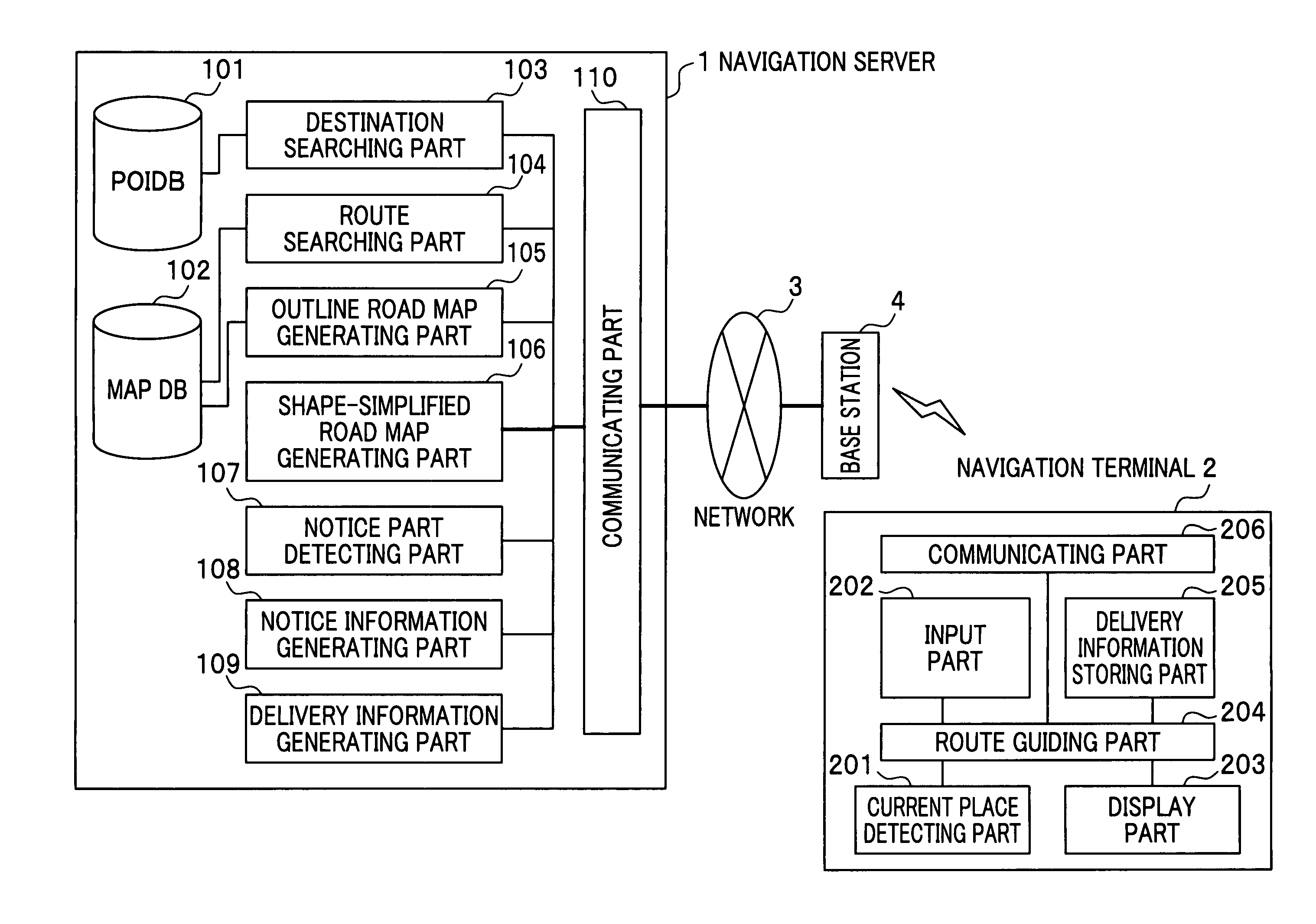
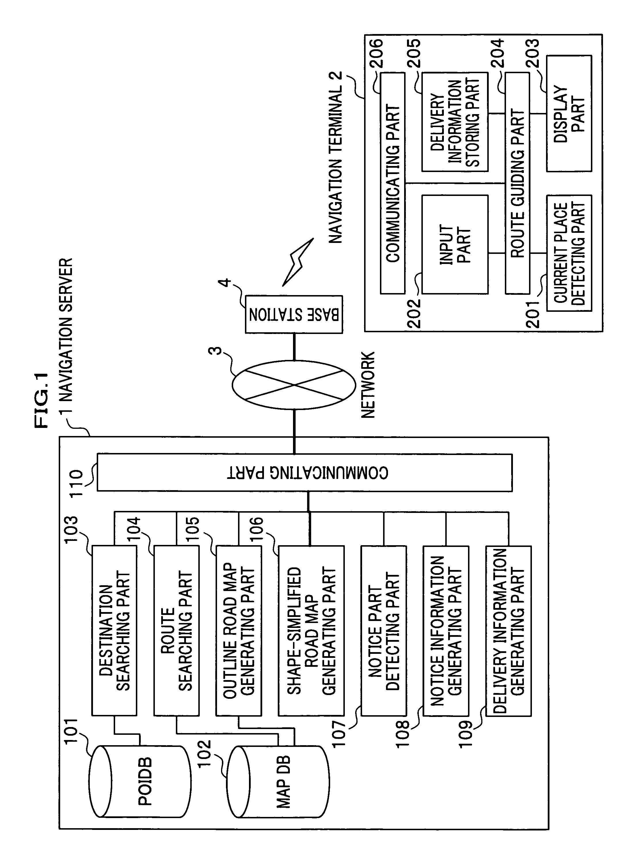
[0043]FIG. 1 is an outline drawing of a navigation system in which an embodiment of the present invention is used.

[0044] As shown in the drawing, the navigation system according to the embodiment is configured by connecting a navigation server 1 and the navigation terminal 2 each other through a network 3. Here, the navigation terminal 2 is connected to the network 3 through a wireless base station 4.

[0045] First, will be described the navigation server 1.

[0046] The navigation server 1 performs a searching process for a guiding route in accordance with an instruction from the navigation terminal 2 and then transmits information of the guiding route as a result of the process to the navigation terminal 2. As shown in FIG. 1, the navigation server 1 includes a POI (Point Of Interest) database (DB) 101, a map database 102, a destination searching part 103, a route searching part 104, an outline road map gen...


PUM


Abstract

A navigation server 1, a map DB 102, a route searching part 104 for searching a guiding route between a departure place and a destination, a shape-simplified road map generating part 106 for generating shape-simplified road map data in which a road shape of the guiding route is simplified, a notice part detecting part 107 for detecting a part of the guiding route as a notice part having a difference grater than a predetermined quantity between the shape of the guiding route in the map data and a shape of the guiding route in the shape-simplified road map data, a notice information generating part 108 for generating, on the basis of the difference at the notice part between the guiding route in the map data and the shape-simplified road map data, a guidance notice information to be supplied to a navigation terminal 2 when a current place reaches the notice part, and a communicating part 110 for transmitting delivery information including the shape-simplified road map data and the guidance notice information are included. This improves a visibility of the guiding route and decrease error recognition of a guiding direction.

Description

TECHNICAL FIELD [0001] The present invention relates to a route guiding technology for a navigation apparatus. BACKGROUND ART [0002] Japanese laid-open patent application publication No. 2001-273526 discloses a navigation apparatus capable of stereoscopically displaying a map around its own vehicle, a destination, an intersection to be guided, and the like. Further, Japanese laid-open patent application publication No. 2002-206928 discloses a navigation apparatus capable of displaying an enlarged map in a vicinity of its-own vehicle and a map of a wide area from the current placeto a destination. DISCLOSURE OF THE INVENTION [0003] The navigation apparatus described in the document mentioned above can provide a user with a map of a desired area such as a vicinity of a user's vehicle through a display screen in detail. However, if the map is displayed as it is, there may be a case that a guiding route having a complicated road shape cannot be recognized rapidly. Accordingly, to rapidl...

Claims


Application Information

Patent Timeline
Patent Type & Authority Applications(United States)
IPC IPC(8): G01C21/30G01C21/00G01C21/34G01C21/36G08G1/0968G08G1/137
CPCG01C21/3629G08G1/096827G01C21/367
Inventor KATO, MANABUATARASHI, YOSHITAKATANIZAKI, MASAAKI
Owner HITACHI LTD
Why Eureka
Eureka Blog
Learn More