
Conforming Air Cell Design and Method of Manufacture

Inactive Publication Date: 2007-12-06
MASSMANN MARK WILLIAM
View PDF6 Cites 42 Cited by
  • Summary
  • Abstract
  • Description
  • Claims
  • Application Information

AI Technical Summary

Benefits of technology

[0012]The present invention is an air-filled device made up of interconnected air cells which, once filled with air, creates a readily conforming supportive surface that equalizes pressure against

Problems solved by technology

This approach has a number of challenges.
First, it is very time-consuming and therefore very expensive.
Dipping of mandrels in a vat of rubber, allowing it to cure, then having to glue both a backing and valve interface to this requires excessive manual labor.
Secondly, the design tries to provide a continuous surface against the user.
This, along with the use of rubber material serves to retain excessive heat against the user, making it uncomfortable over time.
Third, the rubber material is prone to forming leaks, since thickness of the material in any specific location is very hard to control with the dipping process.
Though the manufacturing approach used in these disclosures eliminates the mandrel-dipping process, significant problems remain.
First, it must be trimmed of flash material used to hold the plastic for thermoforming, which can damage it by exposing the thin formed part to a cutting device.
As can be imagined, both the number and close-spacing of the weld lines can become very difficult to execute, resulting in either missed welds or damage to parts that cause additional leaks.
The RF welding process itself is inherently difficult to control and repeat.
Putting enough heat into the weld areas can often result in plastic around the welds being over-heated and melting, or in burning all of the way through on the weld lines.
Not putting enough heat into the welds can result in weak welds, causing leaks after delivery of the product to the user.
Many other factors can render the RF welding process to be defective, such as relative air temperature changes, temperature of the plastic before welding, thickness of plastic before welding, over heating and burn-out of RF tooling electrodes, pressure of the electrodes against the plastic, operator error and the like.
Once successful welds are achieved, final trimming of excess material must be accomplished, which as noted previously can by itself result in damaged parts.
As can be seen from this discussion, the manufacturing process used for U.S. Pat. Nos. 5,596,781 and 5,839,140 still requires much human labor and leaves many opportunities for the air-filled structure to be damaged.
In addition, the design which can be created from this process is very limited.
As corners thin down, parts become more susceptible to leaks, which can be caused even by small imperfections in the plastic sheet.
Finally, the use of RF welding limits both the number of welds and how closely they can be spaced apart, limiting how complex the air flow passages can be and therefore limiting functional complexity of the device.

Method used


Image

  • Conforming Air Cell Design and Method of Manufacture
  • Conforming Air Cell Design and Method of Manufacture
  • Conforming Air Cell Design and Method of Manufacture

Examples


Embodiment Construction

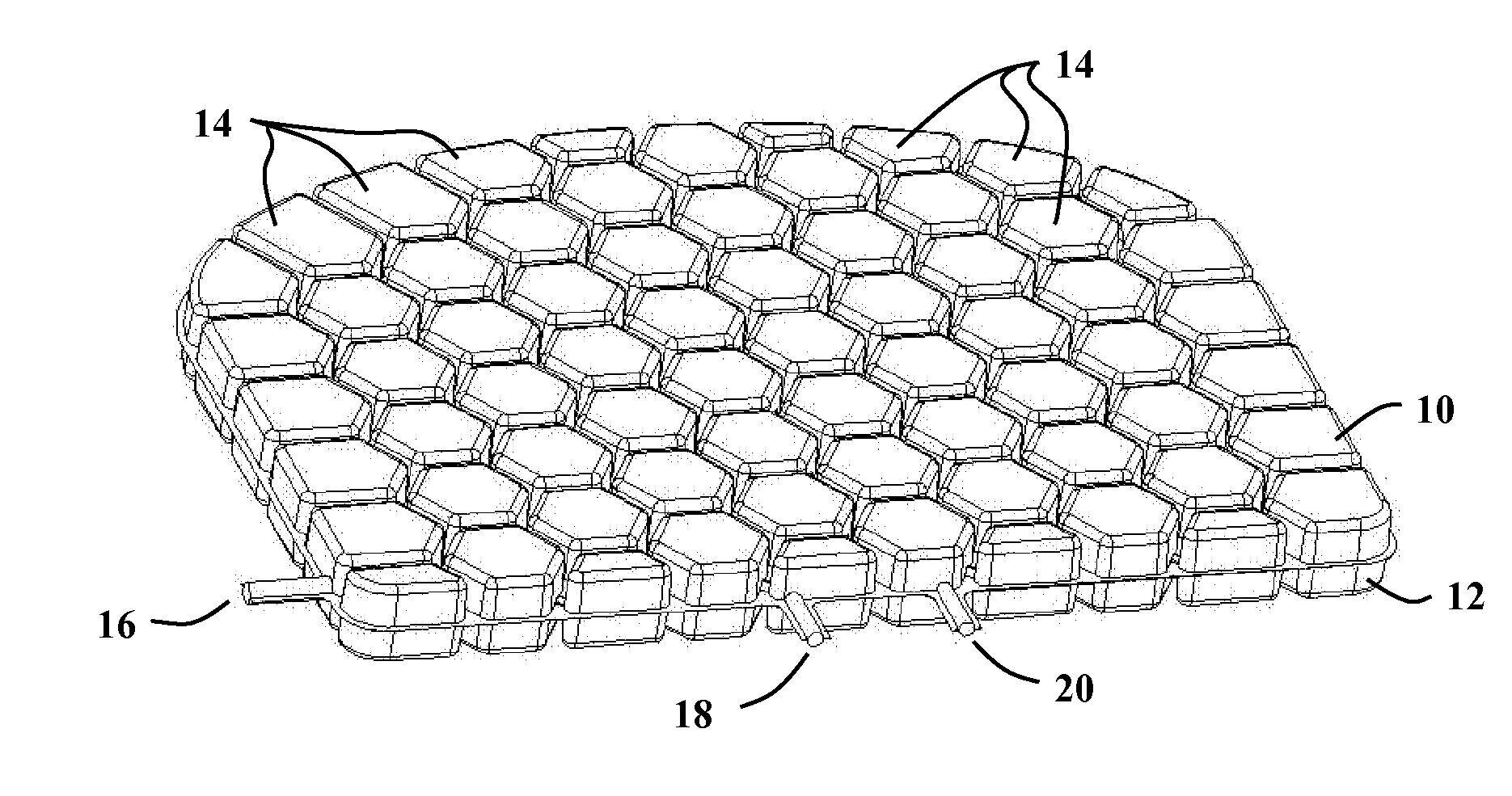
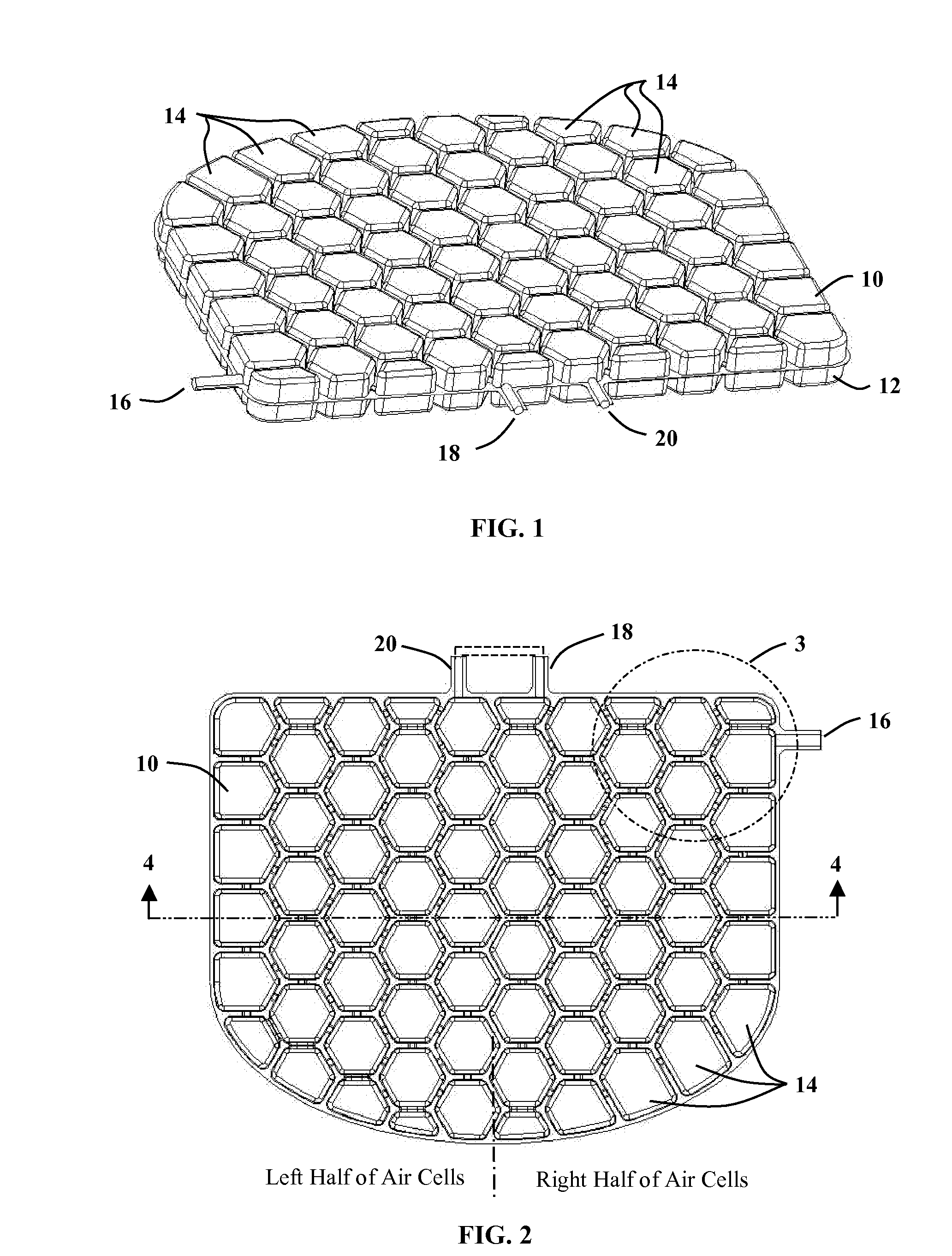
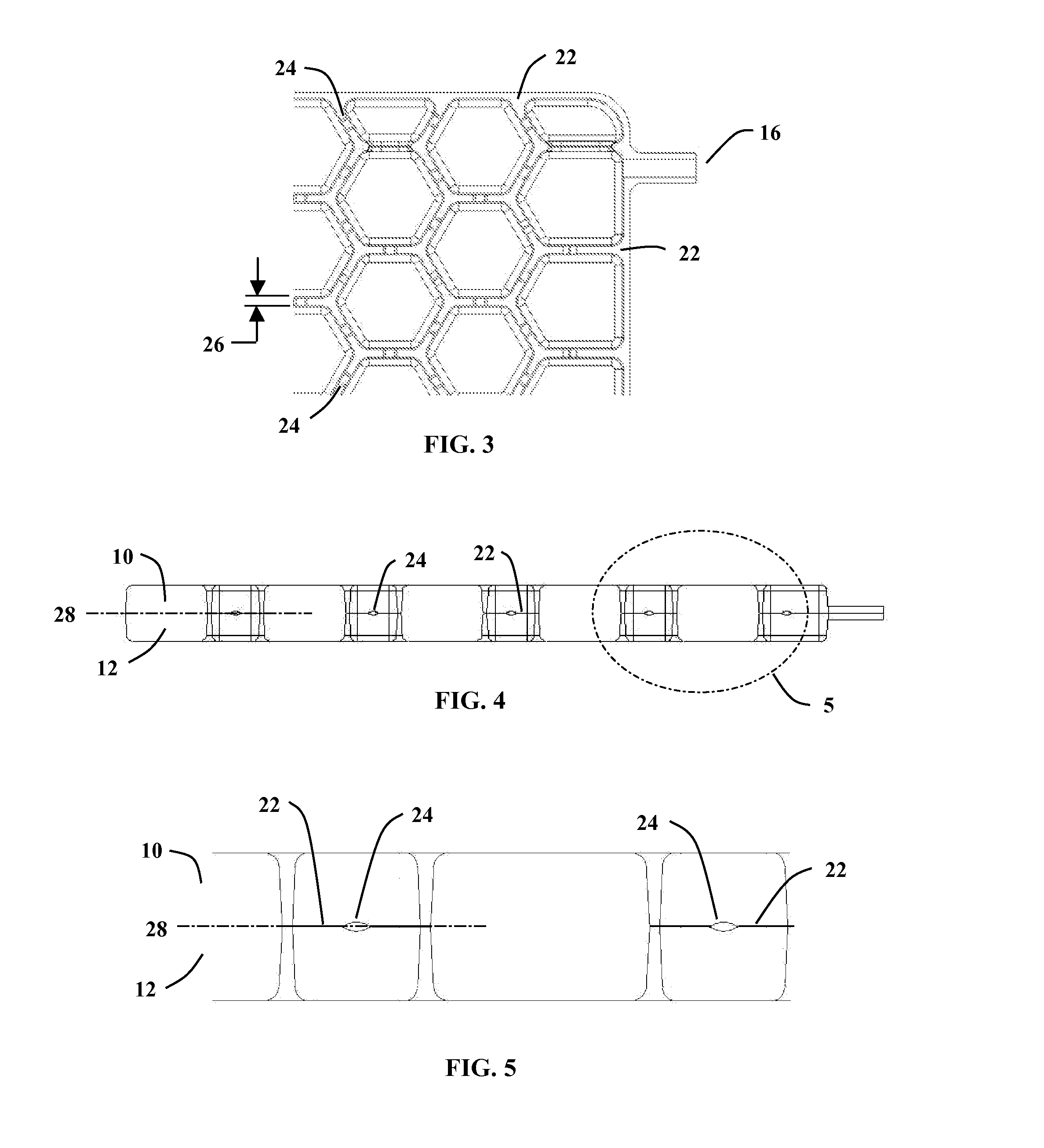
[0021]Referring now to FIG. 1, a perspective view is shown of a preferred embodiment of the invention, in applying the concept for an improved seat cushion. Two thin sheets of highly resilient plastic (approximately 0.010″ thick to 0.040″ thick) are used to form a top half 10 and bottom half 12 in opposing protrusions which when joined, create a multiplicity of individual air cells 14. Plastic types that have the resilient properties desired for the present invention include thermoplastic polyurethanes, highly flexible polypropylenes, soft vinyls, flexible polyethylenes and the like. The intent of the plastic is to create soft, very pliable air cells while being adequately robust to support internal pressures and resist puncture. The plastic could be colored for improved aesthetics, to result in a translucent gray or opaque blue for example. This device could be inserted into a fabric cover to give it a softer feel, customize the look of the seating system, and protect it against da...


PUM


Abstract

A design and method of manufacture for a conforming air cell device to be used for seating, vibration and shock isolation, custom fitting and other applications. Interconnected air cells are formed from two thin sheets of highly resilient thermoformed plastic, so that once inflated, the air cells readily conform to the shape of the user while equalizing pressure from cell to cell. The manufacturing method simultaneously thermoforms both halves of the cell structure, followed immediately by joining these halves while still at the material's forming temperature. The result is a relatively complex matrix of air cells, interconnecting passages and one or more inflation features in a single manufacturing process, greatly simplifying the manufacturing process over previous methods. The design and method of manufacture result in an extremely lightweight, flexible and compactable system that quickly inflates and deflates, and can easily be taken and used anywhere it is needed.

Description

[0001]This document contains the non-provisional submittal for provisional application 60 / 811,641, which had a filing date of Jun. 6, 2006. The provisional application was entitled “Conforming Air Cell Design and Method of Manufacture” authored by Mark Massmann.TECHNICAL FIELD OF THE INVENTION[0002]The present invention relates to supporting devices which provide a surface to support at least a portion of a user's body. Specifically, this invention relates to air-filled supporting devices which readily conform to a user's body, equalizing pressure against the user to provide long-term comfort.BACKGROUND OF THE INVENTION[0003]The field of conforming materials and products is very broad and diverse. However all of these products strive for the same goal, which is to equalize pressure required to support the user so as to reduce or eliminate high pressure points as much as possible. On the human body, these high pressure points inevitably cause discomfort and pain through the restricti...

Claims


Application Information

Patent Timeline
IPC IPC(8): A47C16/00A47C27/10
CPCA47C4/54A47C27/10A47C27/083A47C27/082
Inventor MASSMANN, MARK
Owner MASSMANN MARK WILLIAM
Learn More