Cutting apparatus, honeycomb molded body cutting method, and honeycomb structure manufacturing method
Inactive Publication Date: 2007-12-06
IBIDEN CO LTD
View PDF71 Cites 70 Cited by
Summary
Abstract
Description
Claims
Application Information
AI Technical Summary
This helps you quickly interpret patents by identifying the three key elements:
Problems solved by technology
Method used
Benefits of technology
Benefits of technology
[0026]In the cutting apparatus of the present invention, desirably, the cutting apparatus is provided with two of the cutting disks, thus enabling cutting of both end portions of the honeycomb molded body simultaneously.
Problems solved by technology
Particulates such as soot and the like contained in the exhaust gas expelled by the internal combustion engines of vehicles such as busses, trucks and the like, and construction equipment and the like, have become a problem of recent, in that they cause harm to the environment and the human body.
Method used
Image
Click on the blue label to locate the original text in one second.
Reading with bidirectional positioning of images and text.
Examples
example 1
[0213]First, 250 kg of siliconcarbidepowder having a mean particle diameter of 10 μm, 100 kg of α-type siliconcarbidepowder having a mean particle diameter of 0.5 μm, and 20 kg of organic binder (methylcellulose) were blended together to prepare a powder mixture.
[0214]Next, 12 kg of lubricating agent (UNILUBE, Manufactured by NOF Corp.), 5 kg of plasticizer (glycerin), and 65 kg of water were blended in a separate container to prepare a liquid mixture. Next, using a wet mixer machine, the powder mixture and the liquid mixture were blended together, thereby preparing the wet mixture.
[0215]And the moisture content of the above prepared wet mixture was 14 percent by weight.
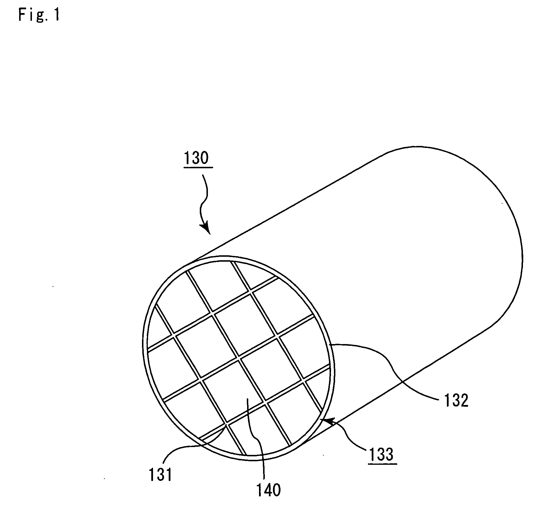
[0216]Next, using a conveyer machine, the wet mixture was conveyed to the extrusionmolding machine, and was then extrusion-molded to produce a molded body having the form shown in FIG. 2.
[0217]Using a microwave dryer or the like, a drying treatment was then administered to the above raw molded body, which thereb...
example 2
[0222]In this embodiment, the only aspect different from Example 1 was that the molded body clamping member uses the mode of molded body clamping member shown in FIG. 4C as the molded body clamping member of the present invention.
reference example 1
[0225]In this example of producing a honeycomb fired body, the hot air drying treatment was not administered before both end portions of the honeycomb molded body were cut, and the microwavedrying treatment was administered after cutting. All other methods used to produce a honeycomb fired body were identical to those of Example 1.
(Measurement of the Full Length of the Honeycomb Fired Body)
[0226]The full lengths of the honeycomb fired bodies produced in Examples 1 and 2, the Comparative Examples 1 and 2, and Reference example 1, 10 samples from each method, were measured using a digital caliper (manufactured by Mitutoyo Corp.) in evaluating the influence that the timing of cutting processing executed to both end portions of the honeycomb molded body, and the order of drying treatment had on the full length of the honeycomb fired body. The results are shown in Table 1.
(Observation of the State of the End Face)
[0227]Using the naked eye, the state of the end faces of the honeycomb fir...
PUM
Property
Measurement
Unit
Thickness
aaaaa
aaaaa
Thickness
aaaaa
aaaaa
Diameter
aaaaa
aaaaa
Abstract
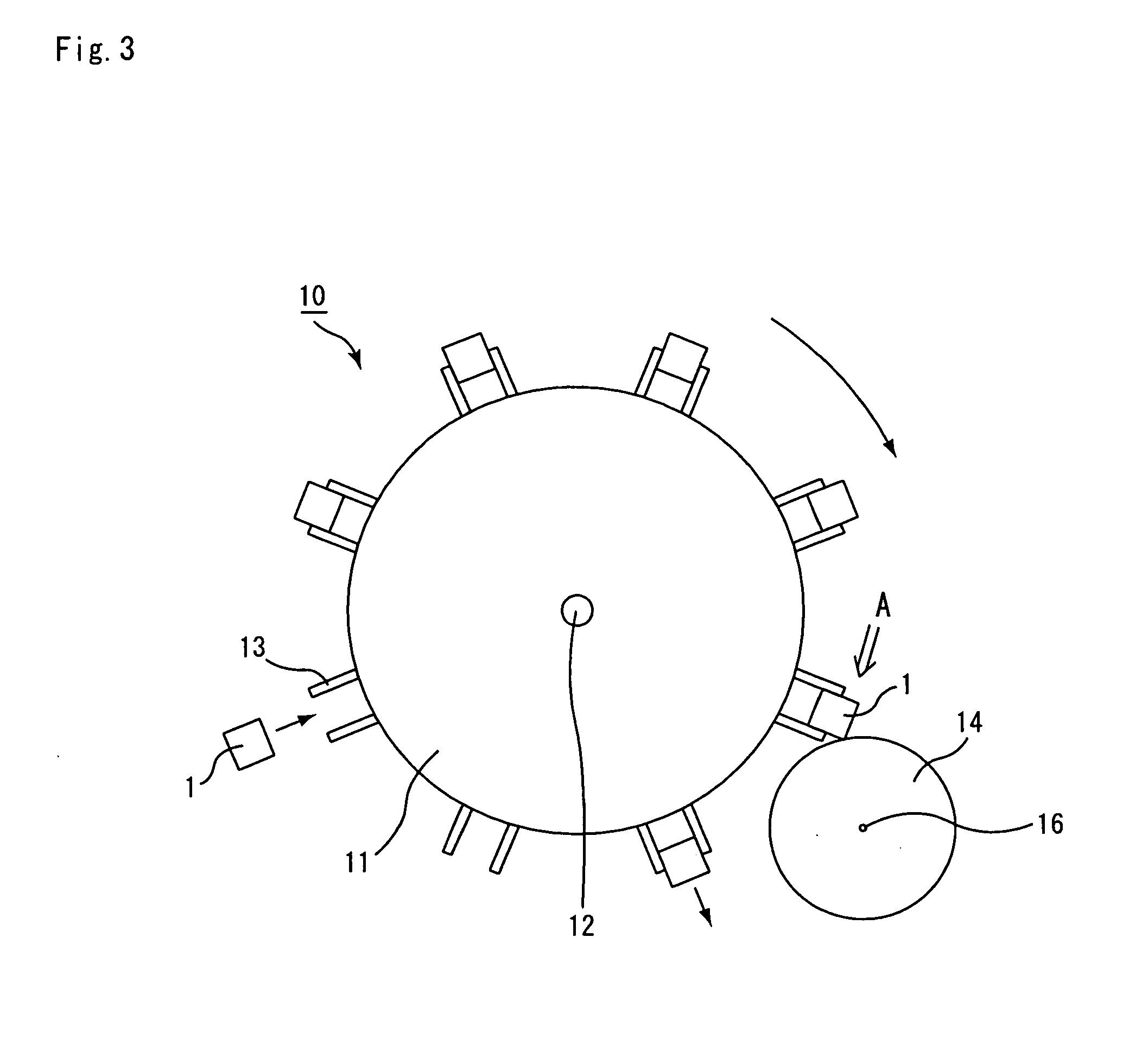
The cutting apparatus of the present invention is a cutting apparatus to execute cutting the end portion of a pillar-shaped honeycomb molded body having multiple cells that are established in rows in the longitudinal direction and partitioned by cell walls, and is provided with a rotary body having a rotary shaft established horizontally, a molded body clamping member configured to clamp the honeycomb molded body established on the rim of the rotary body, and at least one cutting disk, and is configured in such a manner as to execute cutting of an end portion of the honeycomb molded body while the honeycomb molded body, which is clamped by the molded body clamping member, is in a state of being put in motion according to the rotary movement of the rotary body.
Description
CROSS-REFERENCE TO RELATED APPLICATIONS[0001]This application claims benefit of priority based on European Patent Application No. 06114959.7 filed on Jun. 5, 2006. The contents of this application are incorporated herein by reference in their entirety.BACKGROUND OF THE INVENTION[0002]1. Field of the Invention[0003]The present invention relates to cutting apparatuses, methods for cutting a honeycomb molded body, and methods for manufacturing a honeycomb structure.[0004]2. Discussion of the Background[0005]Particulates such as soot and the like contained in the exhaust gas expelled by the internal combustion engines of vehicles such as busses, trucks and the like, and construction equipment and the like, have become a problem of recent, in that they cause harm to the environment and the human body. To remedy this, there are currently being proposed numerous types of honeycomb filters using a honeycomb structure of porous ceramic as a filter for capturing particulates contained in exha...
Claims
Application Information
Patent Timeline
Application Date:The date an application was filed.
Publication Date:The date a patent or application was officially published.
First Publication Date:The earliest publication date of a patent with the same application number.
Issue Date:Publication date of the patent grant document.
PCT Entry Date:The Entry date of PCT National Phase.
Estimated Expiry Date:The statutory expiry date of a patent right according to the Patent Law, and it is the longest term of protection that the patent right can achieve without the termination of the patent right due to other reasons(Term extension factor has been taken into account ).
Invalid Date:Actual expiry date is based on effective date or publication date of legal transaction data of invalid patent.

