
Suspension system having active compensation for vibration

a suspension system and vibration technology, applied in the direction of chairs, machine supports, transportation and packaging, etc., can solve the problems of operator's vibration at higher frequencies, operator's bumpy and jarring ride,

Active Publication Date: 2007-12-06
DEERE & CO
View PDF16 Cites 60 Cited by
  • Summary
  • Abstract
  • Description
  • Claims
  • Application Information

AI Technical Summary

Benefits of technology

[0004]A suspension system for a seat of a vehicle comprises a base, a linkage, and a seat attached to the base via the linkage. A pneumatic shock absorber provides a respective resistance level against movement of the seat with respect to the base based on a corresponding pressure level of air or gas within the pneumatic shock absorber. An output member of a linear motor is connected

Problems solved by technology

However, the operator of the vehicle may be subjected to vibrations at higher frequencies than the response rate of the hydraulic damping.
For example, if the vehicle is operated at sufficiently high speeds, the hydraulic damping may fail to attenuate the vibrations from traveling over the ground; hence, the operator may experience a bumpy and jarring ride.

Method used


Image

  • Suspension system having active compensation for vibration
  • Suspension system having active compensation for vibration
  • Suspension system having active compensation for vibration

Examples


Embodiment Construction

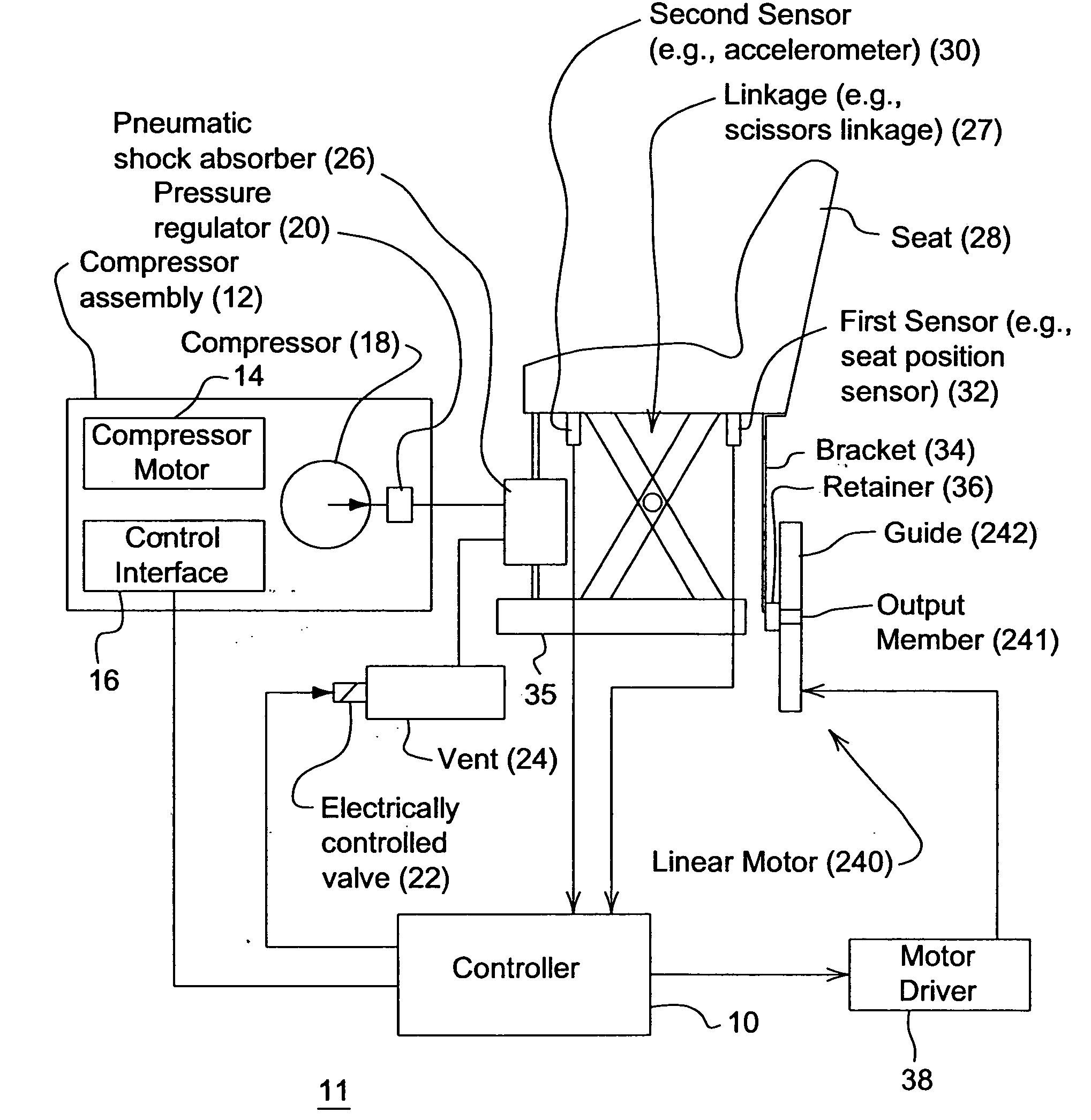
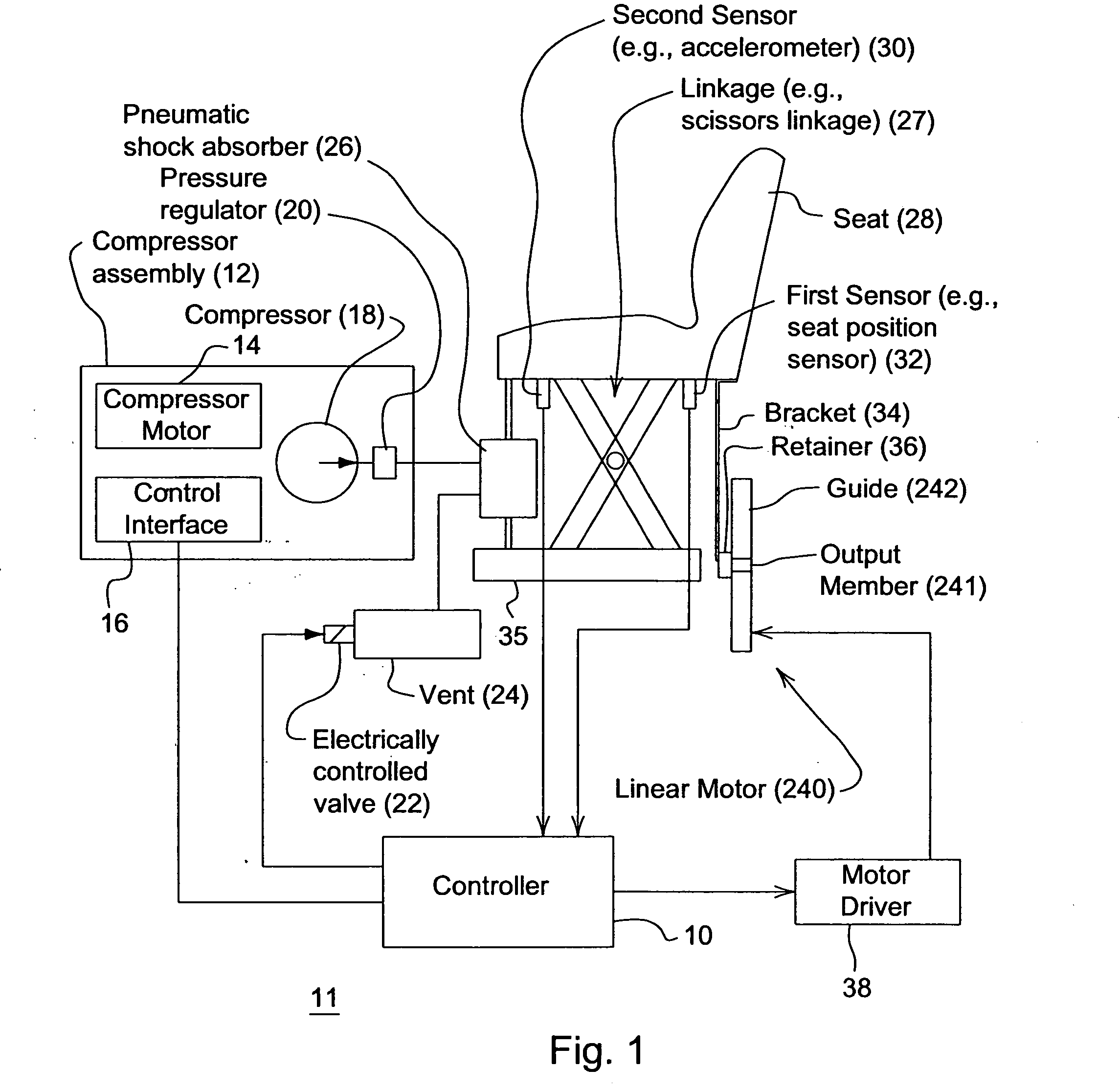
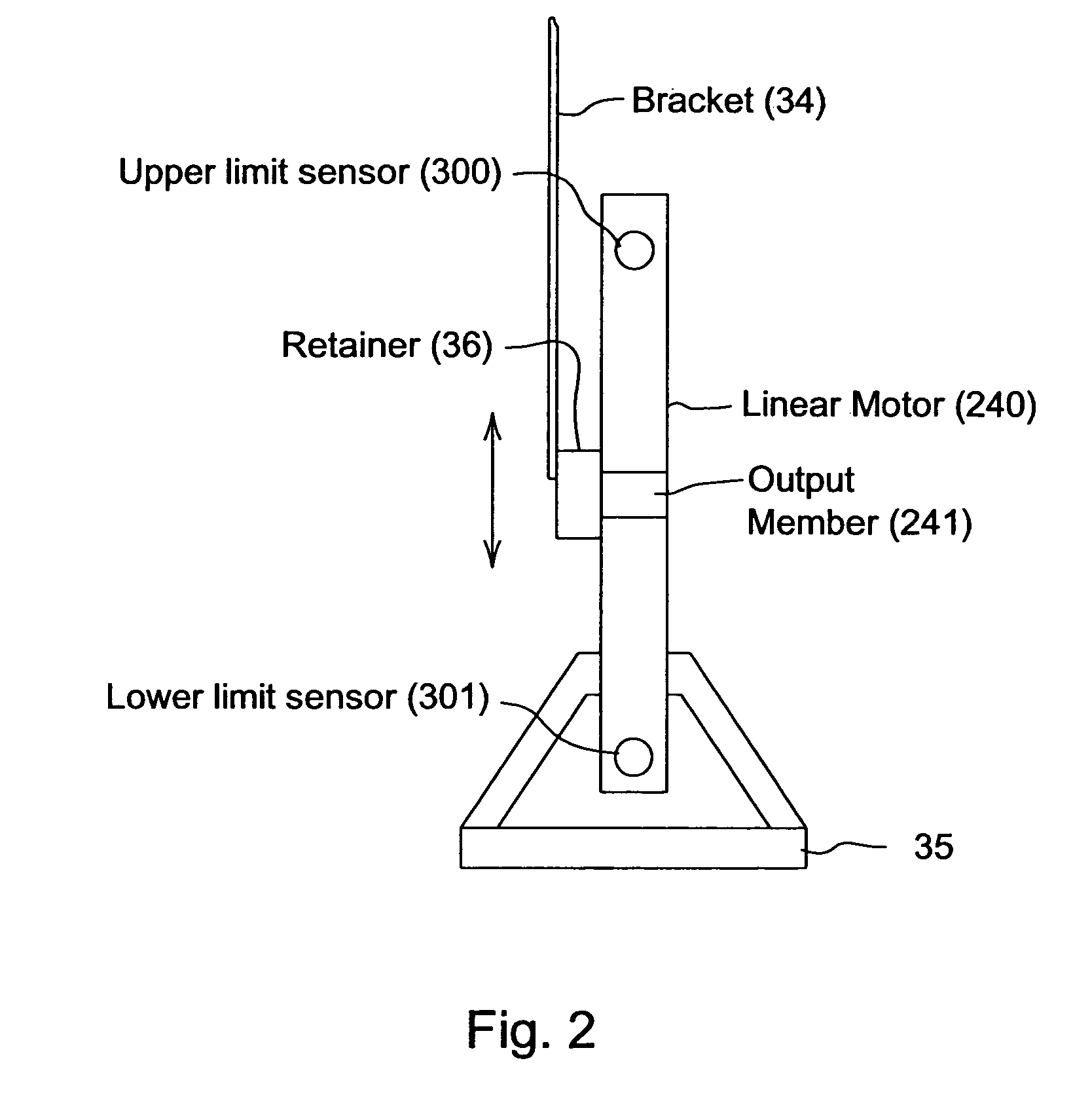
[0009]FIG. 1 illustrates one embodiment of a suspension system 11 for a seat 28 of a vehicle. The suspension system 11 comprises a base 35, a linkage 27, and a seat 28 attached to the base 35 via the linkage 27. In one embodiment, the linkage 27 may comprise a scissors support system, although any suitable support system may be used that allows vertical adjustment of the seat 28. A pneumatic shock absorber 26 provides a respective resistance level against movement of the seat 28 with respect to the base 35 based on a corresponding pressure level of air or gas within the pneumatic shock absorber 26. A linear motor 240 has an output member 241 coupled to a bracket 34 via a retainer 36. The bracket 34 provides a mechanical connection between the output member 241 of the linear motor 240 and the seat 28. In one embodiment, the output member 241 of the linear motor is movable in a generally vertical direction along a guide 242 (e.g., slot) associated with the linear motor 240. A first se...


PUM


Abstract

A suspension system for a seat of a vehicle comprises a base, a linkage, and a seat attached to the base via the linkage. A pneumatic shock absorber provides a respective resistance level against movement of the seat with respect to the base based on a corresponding pressure level of air or gas within the pneumatic shock absorber. An output member of a linear motor is connected to the seat via a bracket. A first sensor is arranged to detect first sensor data associated with an instantaneous position of the seat versus time. A controller generates at least one of a first control signal for the linear motor to change a height of the seat in opposition to a change in the instantaneous position of the seat and a second control signal to change the pressure level.

Description

[0001]This document (including all drawings) claims priority based on U.S. provisional application Ser. No. 60 / 811,335, filed Jun. 6, 2006, and entitled SUSPENSION SYSTEM HAVING ACTIVE COMPENSATION FOR VIBRATION under 35 U.S.C. 119(e).FIELD OF THE INVENTION[0002]This invention relates to a suspension system having active compensation for vibration.BACKGROUND OF THE INVENTION[0003]Suspension systems for seats may use hydraulic damping to reduce the vibration of a seat of a vehicle. However, the operator of the vehicle may be subjected to vibrations at higher frequencies than the response rate of the hydraulic damping. For example, if the vehicle is operated at sufficiently high speeds, the hydraulic damping may fail to attenuate the vibrations from traveling over the ground; hence, the operator may experience a bumpy and jarring ride. Thus, there is a need to provide active compensation for vibration.SUMMARY OF THE INVENTION[0004]A suspension system for a seat of a vehicle comprises ...

Claims


Application Information

Patent Timeline
IPC IPC(8): A47C7/14
CPCB60N2/501B60N2/525B60N2/508
Inventor SHOEMAKER, JIM MILTONSTAHLHUT, RONNIE DEANSCHICK, TROY EUGENEROMIG, BERNARD EDWIN
Owner DEERE & CO
Learn More