Power Supply Circuit, Charge Pump Circuit, and Portable Appliance Therewith

Inactive Publication Date: 2007-12-06
ROHM CO LTD
View PDF5 Cites 42 Cited by
  • Summary
  • Abstract
  • Description
  • Claims
  • Application Information

AI Technical Summary

Benefits of technology

[0053] As described above, with power supply circuits and charge pump circuits according to the present invention, even if the level of the in

Problems solved by technology

One problem with this charge pump circuit is in-rush current at start-up.
In particular in a system having a high-impedance power supply section as in a portable appliance operating fr

Method used


Image

  • Power Supply Circuit, Charge Pump Circuit, and Portable Appliance Therewith
  • Power Supply Circuit, Charge Pump Circuit, and Portable Appliance Therewith
  • Power Supply Circuit, Charge Pump Circuit, and Portable Appliance Therewith

Examples


Embodiment Construction

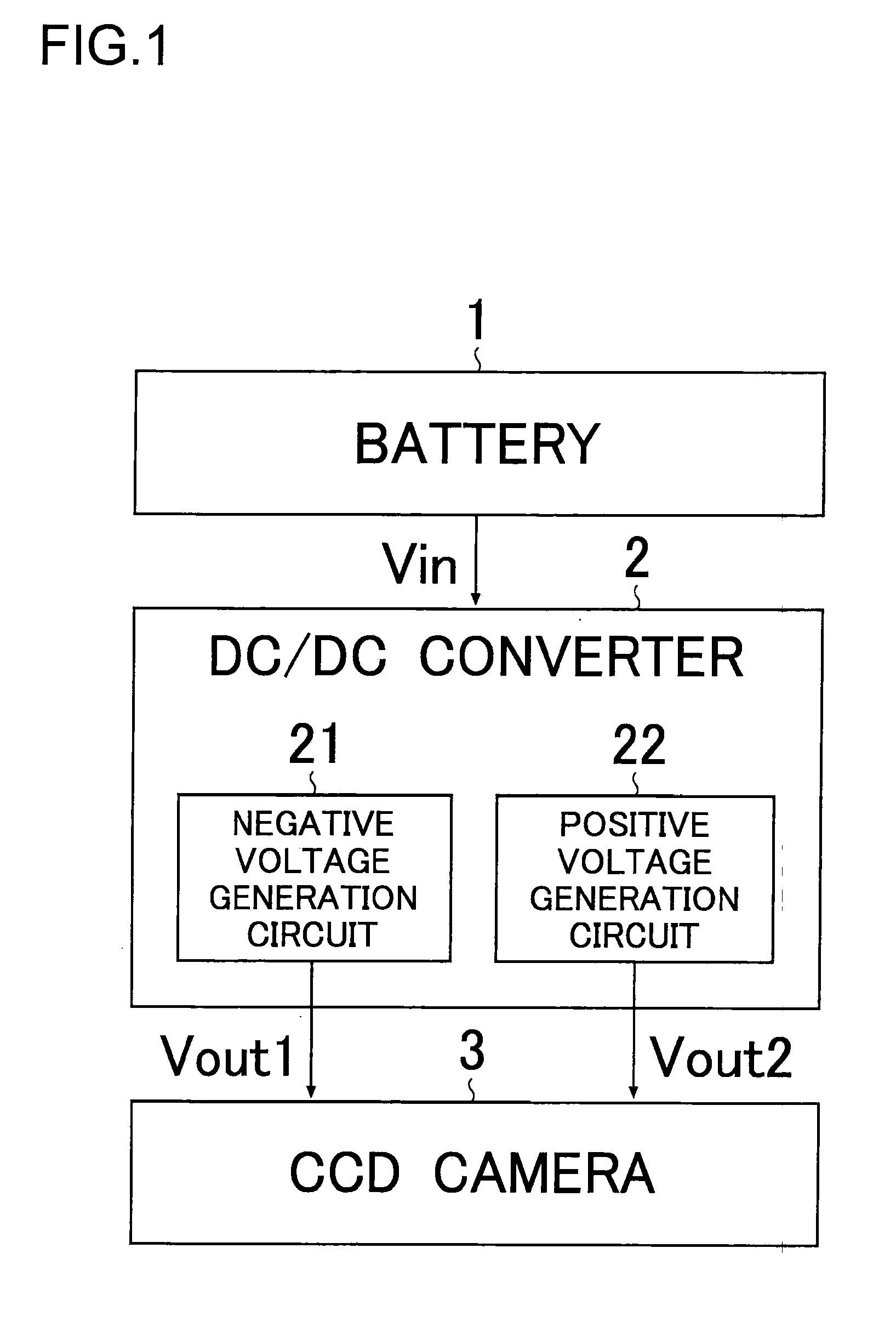
[0072] Hereinafter, the present invention will be described by way of an example in which it is applied to a DC / DC converter that is incorporated in a cellular phone unit to convert the output voltage of a battery to produce a voltage for driving different parts (in particular a CCD—charge-coupled device—camera) of the cellular phone unit.

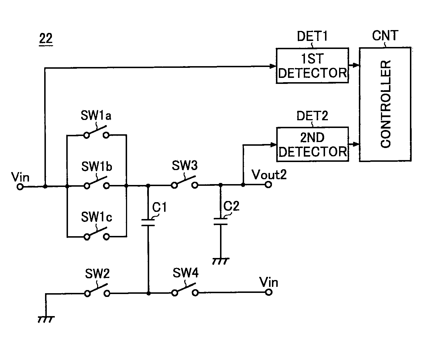
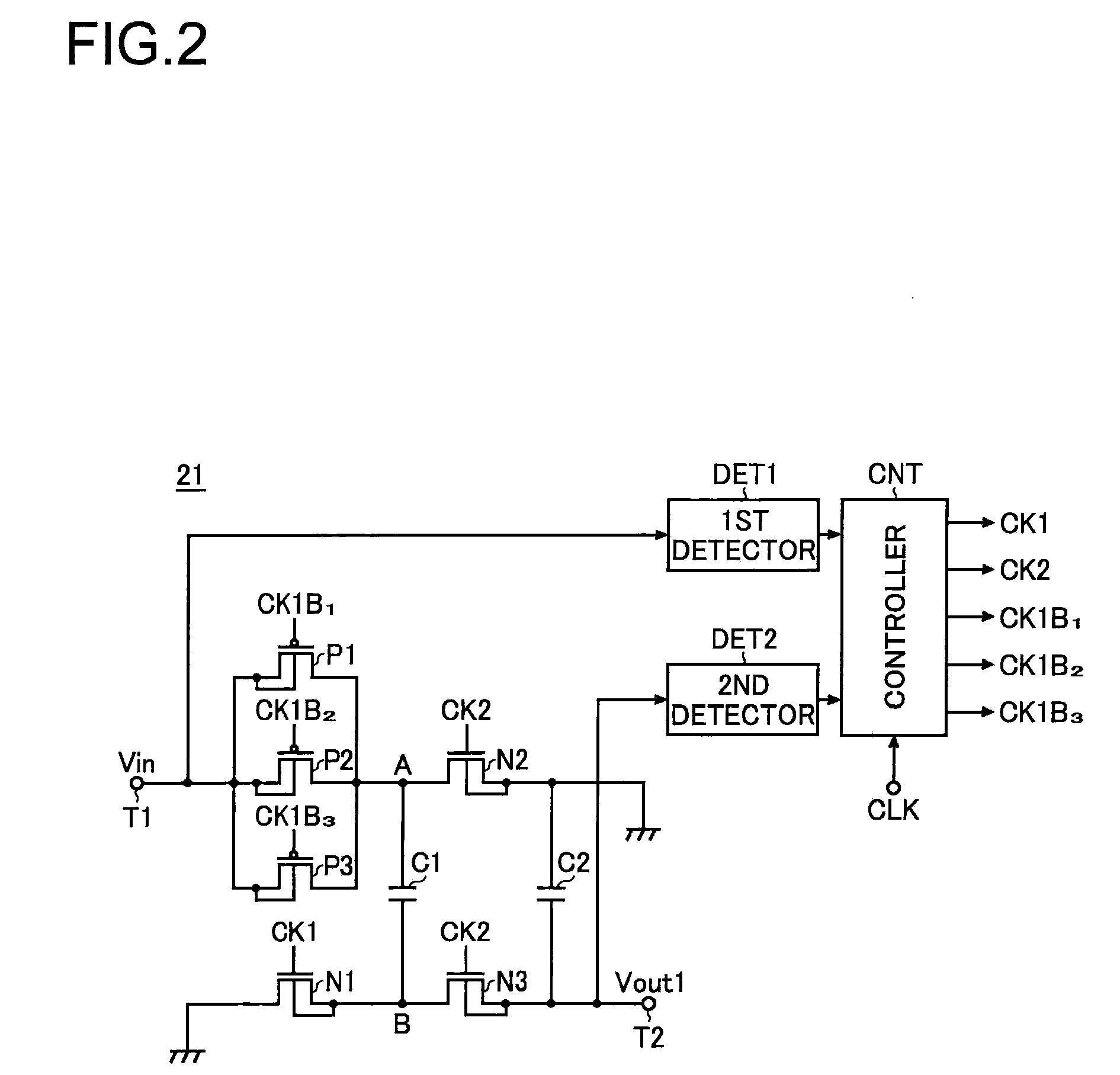
[0073]FIG. 1 is a block diagram showing, as an embodiment of the invention, a cellular phone unit according to the invention (in particular its power supply section for a CCD). As shown in the figure, the cellular phone unit this embodiment includes: a battery 1 serving as an electric power source for the entire cellular phone unit; a DC / DC converter 2 serving as means for converting the output of the battery 1; and a CCD camera 3 serving as means by which the cellular phone unit senses images. Needless to say, in addition to the components already mentioned, the cellular phone unit further includes, as means for achieving its essential functions ...


PUM


Abstract

According to the invention, a charge pump circuit (21) has, as switching means turned on when a capacitor (C1) is charged, transistors (P1 to P3) connected in parallel between one end of the capacitor (C1) and an input terminal (T1). When the capacitor (C1) is charged, a controller (CNT) determines which of the transistors (P1 to P3) to drive based on the results of monitoring of the input and output voltages by first and second detectors (DET1, DET2). Thus, even if the level of the input voltage varies, it is possible to reduce in-rush current at start-up without causing a drop in the output voltage or a loss in efficiency.

Description

TECHNICAL FIELD [0001] The present invention relates to a charge pump circuit used as a DC / DC converter (in particular one used as battery output converting means in a portable apparatus). BACKGROUND ART [0002]FIG. 8 is a circuit diagram showing a conventional example of a charge pump circuit. The charge pump circuit shown in this figure is so configured as to turn on and off switches SW1 to SW4 cyclically in such a way that a first capacitor C1 is charged with an input voltage Vin fed in via an input terminal and that the charge voltage across the first capacitor C1 is then fed out via an output terminal as a negative voltage Vout (−Vin). [0003] More specifically, here, the negative voltage is outputted in the following manner. First the switches SW1 and SW2 are turned on and the switches SW3 and SW4 are kept off. As a result of this switching, the input voltage Vin is applied via the switch SW1 to a first end (point A) of the first capacitor C1, and a second end (point B) of the f...

Claims


Application Information

Patent Timeline
IPC IPC(8): G05F1/00
CPCH02M3/07
Inventor YANAGIDA, OSAMUIMANAKA, YOSHINORI
Owner ROHM CO LTD
Why Eureka
Try Eureka