Optical pressure measuring apparatus

a pressure measurement and optical technology, applied in the direction of fluid pressure measurement by optical means, optical elements, instruments, etc., can solve the problems of complex processing, low deployment density, and large volume of known optical pressure sensors, and achieve simple, efficient and flexible pressure measurement. , the effect of reducing the number of measurement errors

Inactive Publication Date: 2007-12-06
HONG KONG APPLIED SCI & TECH RES INST
View PDF9 Cites 10 Cited by
  • Summary
  • Abstract
  • Description
  • Claims
  • Application Information

AI Technical Summary

Benefits of technology

[0026] The measurement of force or pressure by tracking on the deformation of an optical cavity of a pressure sensor block facilitates simple, efficient and flexible pressure measurement. For example, an optical arrangement can be used to monitor a plurality of pressure sensors.

Problems solved by technology

Disadvantages of piezoelectric pressure sensors include the need of wiring, electrical insulation, the need of electrical power supply and a low deployment density.
For example, optical pressure sensors are known to obviate the need of electrical wiring and insulation, as well as mitigating problems due to electromagnetic interference.
However, known optical pressure sensors are relatively bulky, complicated and require high precision processing for pressure measurements.

Method used


Image

  • Optical pressure measuring apparatus
  • Optical pressure measuring apparatus
  • Optical pressure measuring apparatus

Examples


Embodiment Construction

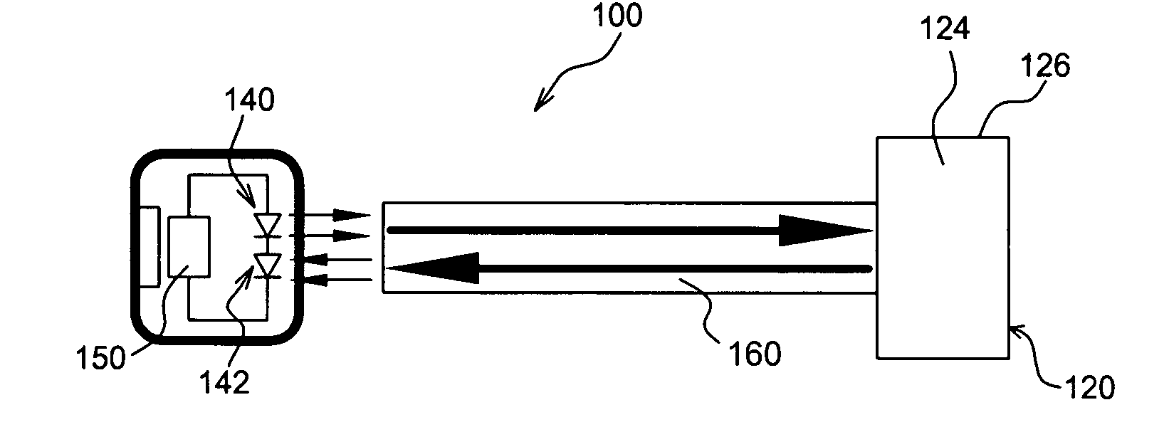
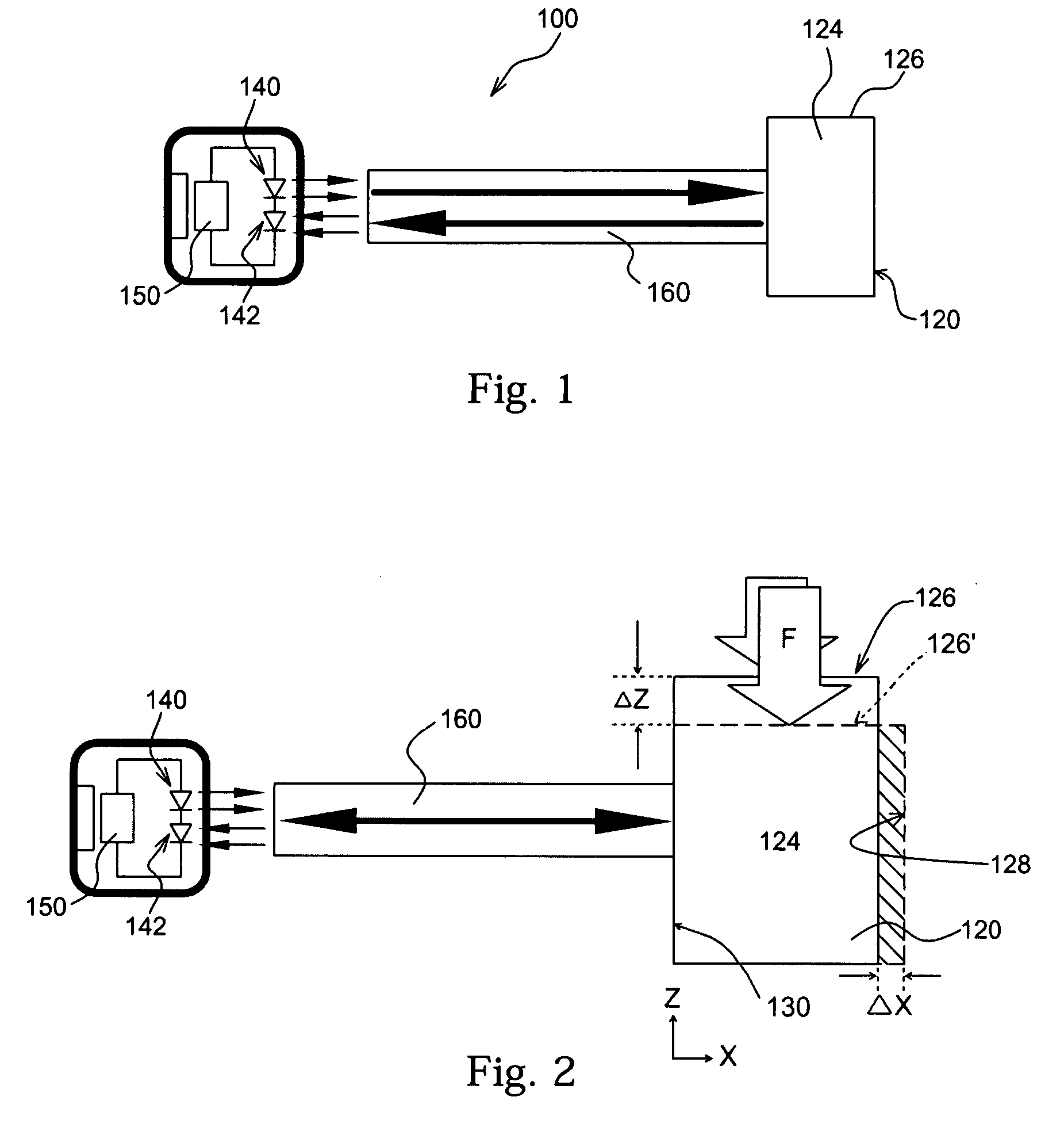
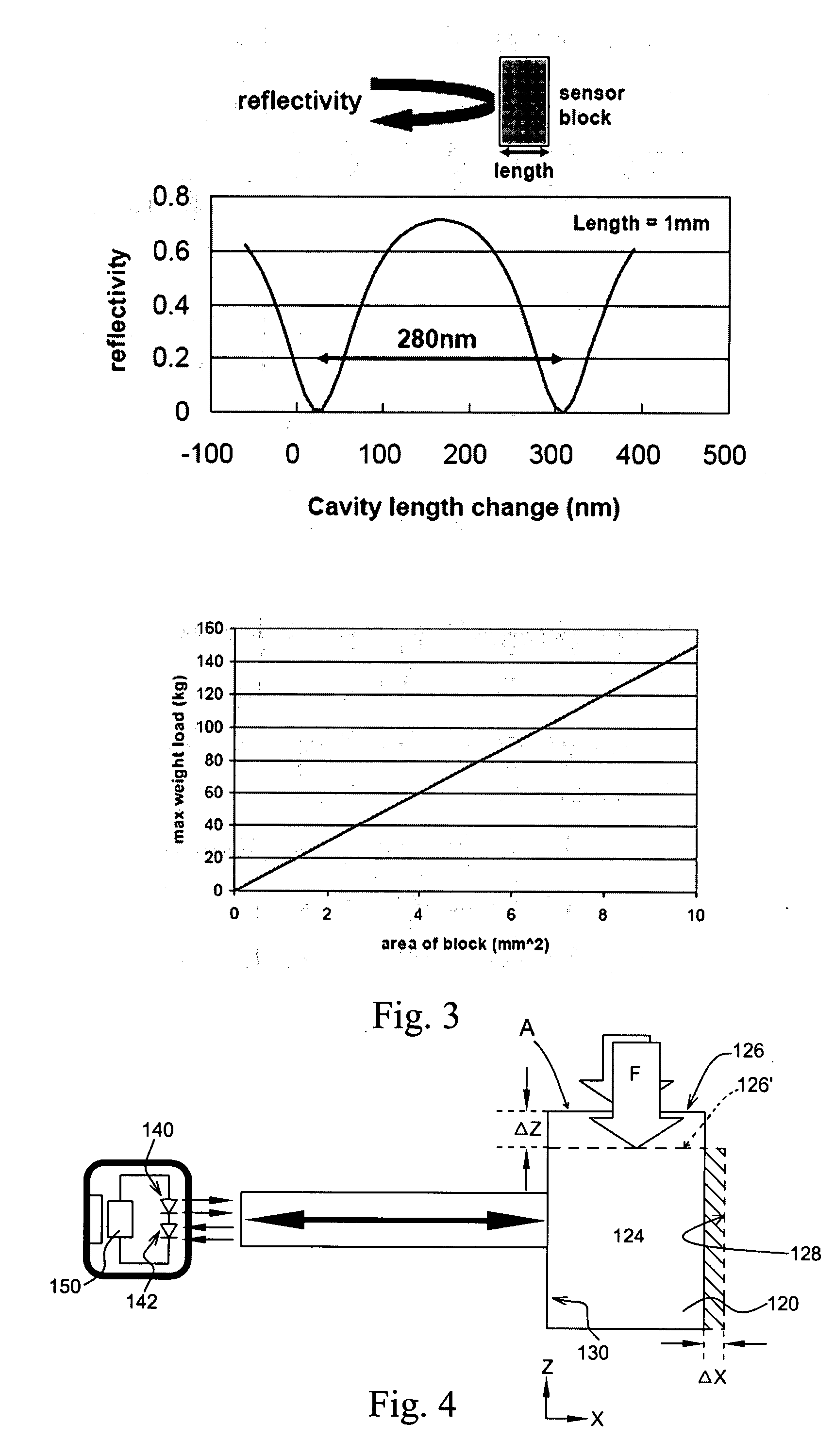
[0033] Referring firstly to FIGS. 1 to 4, there is shown a first preferred embodiment of a pressure measuring apparatus.

[0034] The measuring apparatus 100 comprises a pressure sensing block 120, an optical arrangement comprising an optical source 140 and an optical receiver 142, and a controller 150 with a processor. The pressure sensing block 120 has a pressure sensing surface 122 and an optical cavity 124. The pressure sensing block is rigid and the optical cavity is deformable by application of force on the pressure sensing surface. An exemplary pressure sensing block which is suitable for this application is a transparent prismatic block made of PMMA.

[0035] The optical arrangement comprises an optical source and an optical receiver. The optical source and the optical receiver are arranged for measuring deformation of the optical cavity of the pressure sensing block through optical means.

[0036] The processor is for correlating the extent of deformation of the optical cavity to...


PUM

PropertyMeasurementUnit
lengthaaaaaaaaaa
reflectivityaaaaaaaaaa
lengthaaaaaaaaaa

Abstract

An apparatus comprising an optical cavity for measuring an applied force or pressure, wherein an applied force or pressure is measured or monitored by measuring deformation of said optical cavity when subject to said applied force or pressure.

Description

FIELD OF THE INVENTION [0001] This invention relates to force or pressure measuring apparatus and, more particularly, to optical-based force or pressure measuring apparatus. BACKGROUND OF THE INVENTION [0002] Pressure measurements are important for many applications. For example, pressure measurements are essential for determining the stress conditions, the stress distribution, or load conditions of an object or a structure. In general, pressure measurements are made by pressure sensors which are placed in contact with a load or a pressure source. The physical properties of a typical pressure sensor are a function of the pressure applied onto the pressure sensor. The pressure sensitive physical properties of a pressure sensor are usually transmitted to signal processing circuitry by wire connection. By processing changes in the physical properties of the pressure sensor, pressure parameters can be obtained. [0003] Piezoelectric pressure sensors are probably a better-known type of co...

Claims


Application Information

Patent Timeline
Patent Type & Authority Applications(United States)
IPC IPC(8): G02B6/26G01N21/55
CPCG01L11/02
Inventor WIPIEJEWSKI, TORSTEN
Owner HONG KONG APPLIED SCI & TECH RES INST
Why Eureka
Try Eureka