Equipment position adjusting device

A technology for adjusting the position of devices and equipment, which is applied in the direction of desks or desks, desks, workbenches, etc. of computer workstations, and can solve problems such as physical strain, users' reluctance to adjust, and depressive atmosphere

Active Publication Date: 2017-01-11
HANGZHOU LIERKANG FURNITURE DESIGN CO LTD
View PDF10 Cites 1 Cited by
  • Summary
  • Abstract
  • Description
  • Claims
  • Application Information

AI Technical Summary

Problems solved by technology

[0004] (1) The position adjustment of the monitor, the keyboard and the mouse is related, because the mechanical parts that physically connect the monitor and the keyboard and the mouse tray are used, when the user operates the keyboard and the mouse, the shaking of the keyboard and the mouse tray passes through the The mechanical parts are transmitted to the display, which inevitably leads to the shaking of the display, making it difficult to see the display, causing discomfort, which is not conducive to the use of the user
Although the user can carefully use the keyboard and mouse, and minimize the shaking to the extent that they are hard to detect, this kind of carefulness has caused the user's tension virtually, which is not conducive to the concentration of the work, reduces the work efficiency, and makes the user nervous. The state is easy to cause physical strain;
[0005] (2) When the device is used to operate the equipment in a standing position, because all the weight of the user's body acts on the lower limbs, it is easy to cause fatigue in the lower limbs, which reduces the user's standing time, and even does not want to use the device to switch between sitting and standing positions, and the device loses partial meaning
When the user feels the fatigue of the lower limbs in a standing posture, it is natural to want to lean / support the upper body on a firm place to reduce the fatigue of the lower limbs, but the current devices on the market cannot provide such a leaning / supporting position, or after leaning / supporting due to the first The reason mentioned in point 1 is that the shaking caused by leaning / supporting is transmitted to the display through the connected mechanical parts, causing the display to shake or even fall;
[0006] (3) Not providing enough support for the arm
Some devices currently on the market make the user operate the keyboard and mouse in a single posture, and do not provide enough support for the arm, or due to the reasons mentioned in point 1, the shaking caused by the support is transmitted to the display through the connected mechanical parts, Cause the display to shake or even drop;
[0007] (4) Some devices currently on the market take up a relatively large space, even when the device is adjusted to the state where the space is the smallest, the space is still relatively large
A large space on the horizontal plane usually results in the user having to vacate more space to install and place devices, and a large vertical space usually hinders the line of sight, destroys the aesthetics, and creates a depressing atmosphere
Both of these footprints adversely affect the flexibility of device deployment and adaptability to different environments
Some devices currently on the market try to solve the problem of taking up a lot of space. They use the method of partial contraction during adjustment to make it take up less space in a certain direction when adjusting to the state that occupies the smallest space. For some reason, it may enter the retraction stroke, resulting in injury or loss;
[0008] (5) The adjustment is not labor-saving and convenient enough, causing the user to be unwilling to adjust, and the device loses its meaning

Method used


Image

  • Equipment position adjusting device
  • Equipment position adjusting device
  • Equipment position adjusting device

Examples


Embodiment 1

[0096] Referring to the attached picture: Figure 1-Figure 8 .

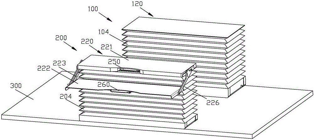
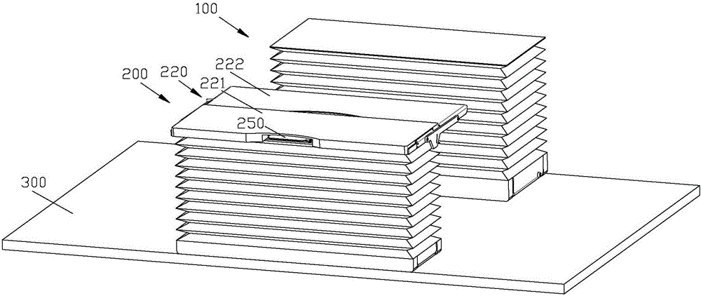
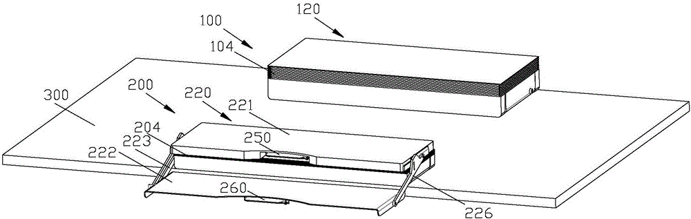
[0097] Such as figure 1 , figure 2 , image 3 As shown, the equipment position adjustment device includes two lifting devices 100, 200 that are arranged on the horizontal bottom surface 300 and only perform telescopic movement in the vertical direction. There is a gap between the devices 100, 200;

[0098] It also includes a first top assembly 120 for placing equipment that needs to avoid shaking and a second top assembly 220 for placing equipment that can shake during operation, and the first top assembly 120 and the second top assembly 220 are respectively installed on two a lifting device 100, 200;

[0099] The lifting device 100, 200 drives the first top assembly 120 and the second top assembly 220 to move only in the vertical direction, and the angles between the first top assembly 120 and the second top assembly 220 and the horizontal bottom surface 300 remain unchanged;

[0100] The second top assem...

Embodiment 2

[0233] Refer to attached Figure 12 , Figure 13 as well as Figure 1-Figure 8 .

[0234] The difference between this embodiment and embodiment 1 is that the structure of the lifting device is different.

[0235] Such as Figure 12 , Figure 13 , the lifting device includes a second base 101b and a second top plate, the second major axis 151 is parallel to the second base 101b, and the first oblique rod 147 and the second oblique rod 148 are respectively rotatably sleeved on the second major axis 151 at both ends, and the first slanting rod 147 and the second slanting rod are arranged crosswise;

[0236] The bottom end of the first inclined rod 147 is rotatably arranged on the second base 101b through the second transverse axis 142b, and the second transverse axis 142b is parallel to the second major axis 151; the bottom end of the second inclined rod 148 passes through the first the sliding hinge device is slidably arranged on the second base 101b;

[0237] The top end...

Embodiment 3

[0270] Refer to attached Figure 14 as well as Figure 1-Figure 8 .

[0271] The difference between this embodiment and Embodiment 1 is that the structure of the lifting device is different.

[0272] as attached Figure 14 As shown, the lifting device includes a third base 101c and a third top board, and also includes several sets of hinged rod combinations hinged between the third base 101c and the third top board. In this embodiment, two groups of hinged rod combinations are preferred; The rod combination includes several groups of X-shaped brackets that are hinged up and down. In this embodiment, a preferred group of hinged rod combinations includes 2 groups of X-shaped brackets; The long rods 149c, 159, 158, 148c are cross-hinged;

[0273] Two X-shaped supports adjacent up and down are formed by the end of the first long rod 157,160 of the X-shaped support above, the end of the second long rod 159,158 and the second long rod of the X-shaped support below. The top ends...


PUM


Abstract

The invention relates to an equipment position adjusting device. A first top assembly and a second top assembly are mounted on two lifting devices, respectively; the lifting devices drive the first top assembly and the second top assembly to move only along the vertical direction, and the included angles between the first top assembly and the horizontal bottom surface and the second top assembly and the horizontal bottom surface are maintained unchanged; a supporting assembly is fixed on one of the lifting devices, a tray revolves around the supporting assembly through a locating adjusting mechanism, and the included angle between the tray and the horizontal bottom surface in the revolving process is maintained unchanged; the rotating track of the tray is a curve around the supporting assembly, one side, far from the first top assembly, of the second top assembly is defined as a using side where a user is during use, and the lowest point of the curve located on the using side is lower than the supporting assembly. The equipment position adjusting device further comprises a first locking device and second locking device. Both the first locking device and the second locking device are connected to unlocking devices.

Description

technical field [0001] The invention relates to a device position adjustment device. Background technique [0002] With the development of society, ergonomics has been paid more and more attention. Especially when human beings enter the information age, daily work and life are increasingly dependent on operating computers and other equipment. However, the relative position of many devices to the human body is not adjustable, and users of different sizes cannot use the devices in an ergonomically suggested manner. In addition, this non-adjustability forces the user to operate the device in the same posture for a long time, which can easily lead to health problems such as cervical spine and lumbar spine injuries. Studies have shown that changing your posture at regular intervals, such as alternating sitting and standing, has health benefits. Therefore, there is an urgent need for a technical solution for conveniently adjusting the relative position of the device and the hum...

Claims


Application Information

Patent Timeline
Patent Type & Authority Applications(China)
IPC IPC(8): B25H1/16A47B21/02
CPCA47B21/02B25H1/16
Inventor 向超
Owner HANGZHOU LIERKANG FURNITURE DESIGN CO LTD
Why Eureka
Try Eureka