Method of Packet Switched Handover

Active Publication Date: 2007-12-06
NOKIA TECHNOLOGLES OY
View PDF6 Cites 16 Cited by
  • Summary
  • Abstract
  • Description
  • Claims
  • Application Information

AI Technical Summary

Benefits of technology

[0011] Preferably, a start time for the terminal to access a target cell in the packet sw

Problems solved by technology

During this procedure PS data cannot be received by the mobile thus increasing the PS service interruption time.
This procedure ca

Method used


Image

  • Method of Packet Switched Handover
  • Method of Packet Switched Handover
  • Method of Packet Switched Handover

Examples


Embodiment Construction

[0016] Reference will now be made in detail to the preferred embodiments of the present invention, examples of which are illustrated in the accompanying drawings, wherein like reference numerals refer to like elements throughout.

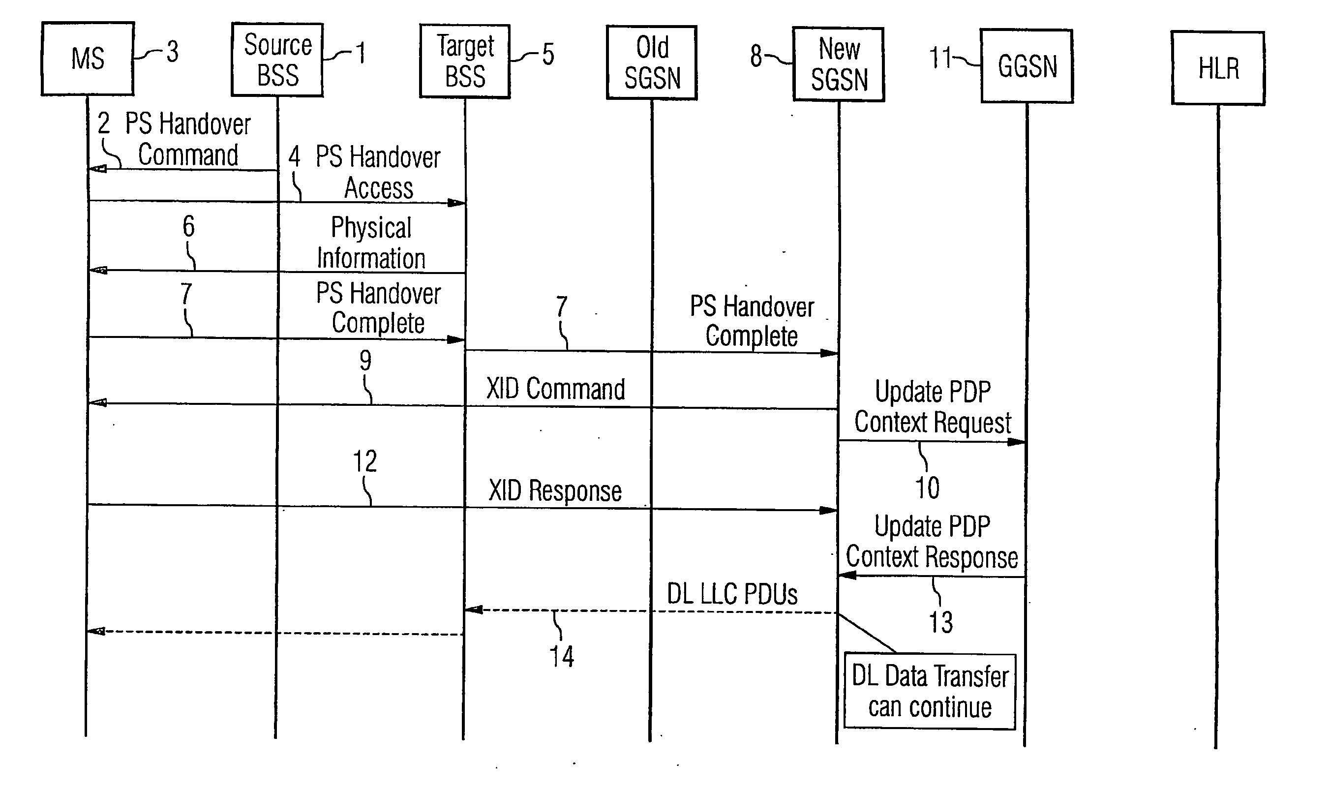
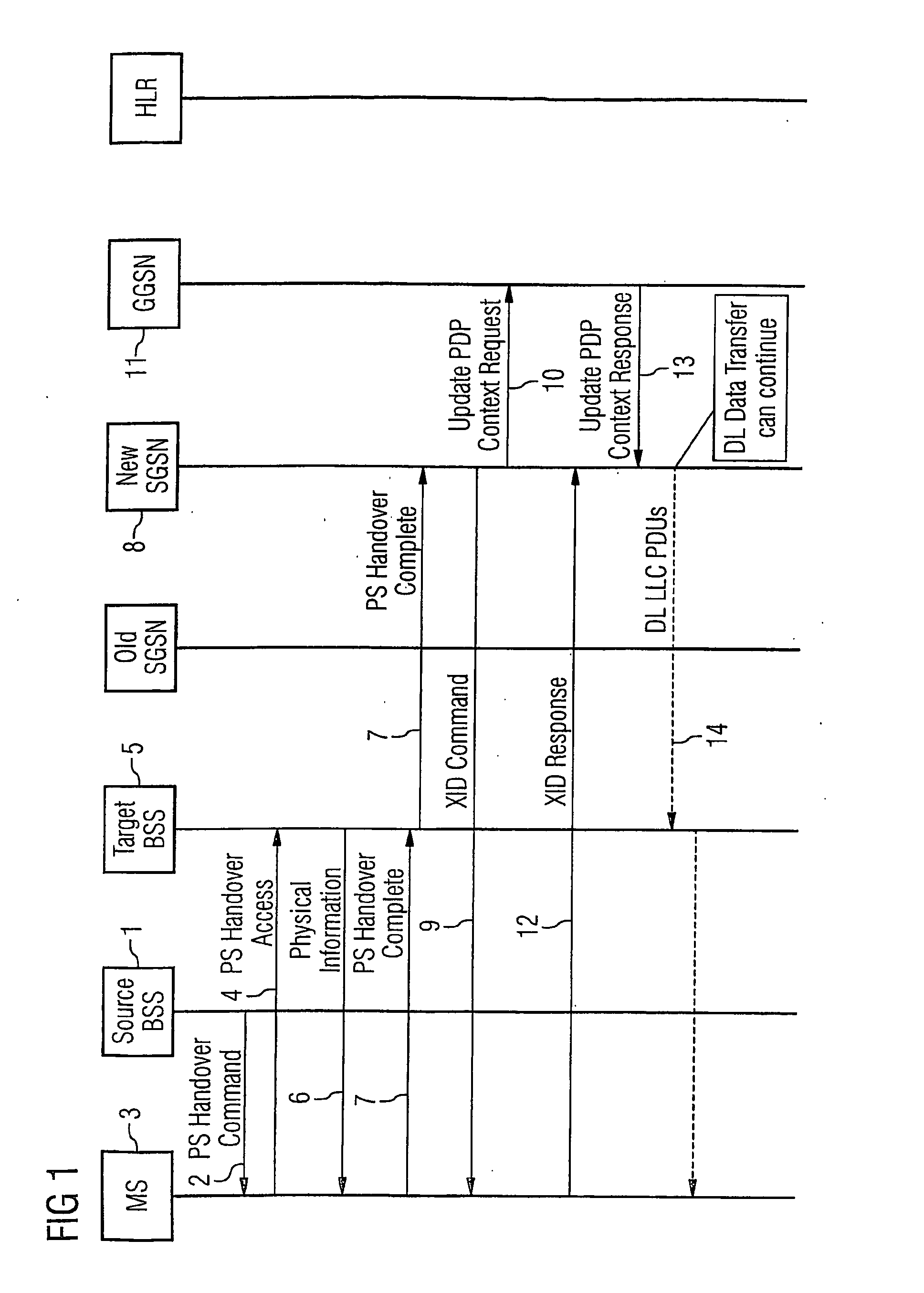
[0017]FIG. 1 illustrates the conventional steps for inter-SGSN packet switched (PS) handover XID procedure after access to a target cell. A source base station 1 sends a PS handover command 2 to a mobile station 3. The mobile station (MS) replies with a PS handover access message 4 to a target base station system (BSS) 5 which sends physical information 6 back to the MS. The MS then sends a PS handover complete message 7 to the target BSS, which sends this message on to a new serving GPRS support node (SGSN) 8. Only once the PS handover is complete does a procedure for negotiating new parameters begin. This is done by the new SGSN 8 sending an exchange identification (XID) command 9 to the MS and an update packet data protocol (PDP) context request 10 to a ...


PUM


Abstract

A method of packet switched handover in a mobile communication system comprising a terminal, a source node and a destination node comprises negotiating protocol parameters for the destination node on behalf of a new network entity, by communicating with an old network entity whilst the terminal is still connected to the source node; and completing the packet switched handover, such that service interruption on handover is reduced.

Description

CROSS REFERENCE TO RELATED APPLICATIONS [0001] This application is based on and hereby claims priority to PCT Application No. PCT / GB2005 / 000697 filed Feb. 24, 2005, Great Britain Application No. 0405389.8 filed on Mar. 11, 2004 and Great Britain Application No. 0414717.9 filed on Jul. 1, 2004, the contents of which are hereby incorporated by reference.BACKGROUND OF THE INVENTION [0002] This invention relates to a method of packet switched handover in a mobile communication system, in particular for 2nd and 3rd generation mobile phone systems, using general packet radio service (GPRS). [0003] Packet Switched (PS) handover is a relatively new topic in Global System for Mobile communications (GSM) / Enhanced Data rates for GSM Evolution (EDGE) Radio Access Network (GERAN) requiring new mechanisms in the RAN and Core Network. PS handover requires low PS service interruption times, preferably less than 200 ms. In the case of inter-SGSN handover the new SGSN (serving general packet radio s...

Claims


Application Information

Patent Timeline
IPC IPC(8): H04Q7/20H04L12/56H04W36/12H04W36/18
CPCH04W36/18H04W36/12
Inventor DAVIS, SIMON PAUL
Owner NOKIA TECHNOLOGLES OY
Why Eureka
Try Eureka