Solar radiation modular collector

a technology of solar radiation and modular collectors, which is applied in the direction of solar heat collectors, heat collector mounting/supports, solar-ray concentration, etc., can solve the problems of inability to modularly insulate thermally the radiation receiving pipe, high cost and complexity of sealing the metal pipe of the receiver with the glass envelope, and low strength of the glass envelope, etc., to achieve the effect of simplifying the manufacturing process of metal envelopes and reducing heat loss

Inactive Publication Date: 2007-12-13
LEVIN ALEXANDER
View PDF17 Cites 13 Cited by
  • Summary
  • Abstract
  • Description
  • Claims
  • Application Information

AI Technical Summary

Benefits of technology

[0027] The gap between the elongated connection straps is preferably glazed in order to diminish heat losses, which occur from the part of the radiation receiving pipe that is not enclosed by the cylindrical sub-section of the internal elongated section.
[0028] According to preferred embodiments, a plurality of metal envelopes may optionally be installed sequentially around a radiation receiving pipe in place of a single envelope. Each such envelope is preferably constructed as described previously. This simplifies the manufacturing process of the metal envelopes.

Problems solved by technology

Sealing the metal pipe of the receiver with the glass envelope is very expensive and complicated from the technological point of view.
It is impossible to insulate thermally the radiation receiving pipe in a modular manner.
Low strength of the glass envelope does not permit this glass envelope to be used as a carrying element of the construction of a solar collector.
These same drawbacks are also true for solar collectors which feature compound-curvature dish-type concentrators.
However, this patent has numerous drawbacks, a few of which are listed below It does prevent heat loss from the receiving pipe due to infrared radiation.
It does not permit enclosure of the majority of the receiving pipe by the thermo-insulating envelope (in fact, the thermo-insulating envelope encloses less than 50% of the surface of the receiving pipe).
It does not permit the internal reflecting surface of the envelope to be used as a secondary non-imaging concentrator.
Pei does not teach any technical solution of tracking the reflector after the sun motion.

Method used


Image

  • Solar radiation modular collector
  • Solar radiation modular collector
  • Solar radiation modular collector

Examples


Embodiment Construction

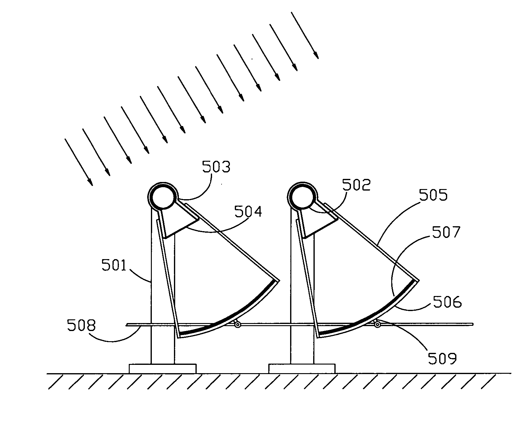
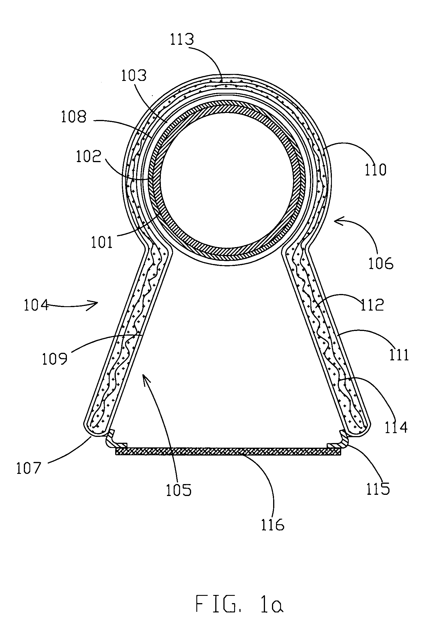
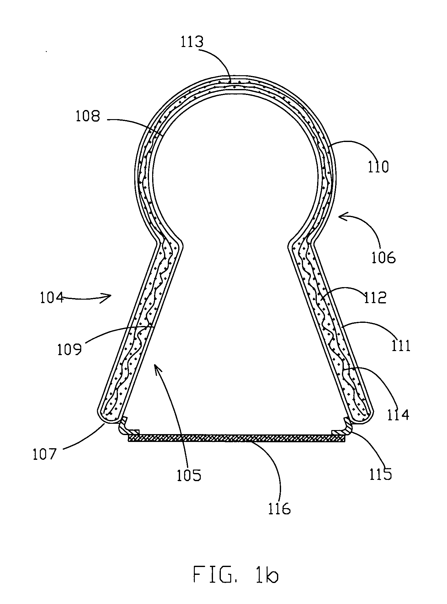
[0088]FIG. 1a, FIG. 1b and FIG. 1c show the transverse cross-sections of the receiver of concentrated solar radiation for the embodiment of the present invention featuring a concentrating single-curvature unit. The figures show an exploded transverse cross-section of the metal envelope of the receiver and its glazing and an exploded transverse cross-section of a radiation receiving pipe of the receiver.

[0089] This embodiment of the device according to the present invention includes a radiation receiving pipe 101 with a selective coating 102 of its outer surface and low circular ribs 103, and a metal envelope 104. Preferably coating 102 is made of selective coating material (preferably absorbing strongly in the visible range but only weakly emitting in the infra-red range of light). As previously described, radiation receiving pipe 101 receives radiation and is insulated by metal envelope 104.

[0090] Metal envelope 104 includes an internal elongated section 105 and an external elong...


PUM


Abstract

The invention relates to the field of solar radiation collectors intended to convert energy of solar radiation into thermal energy, specifically, to the solar radiation collectors constructed as the combination of a concentrated solar radiation receiver, a single-curvature or compound-curvature concentrator and a tracking mechanism. A thermal insulation of the concentrated solar radiation receiver and the concentrated solar radiation receiver itself play a role of parts in the tracking mechanism.

Description

[0001] This Application is a Continuation-in-Part Application of U.S. patent application Ser. No. 11 / 081,406 filed on 17 Mar. 2005, which is hereby incorporated by reference as if fully set forth herein.FIELD OF THE INVENTION [0002] The present invention relates to the field of solar radiation collectors intended to convert energy of solar radiation into thermal energy. BACKGROUND OF THE INVENTION [0003] Solar radiation collectors which convert energy of solar radiation into thermal energy are known. Some types of such collectors include those which incorporate single-curvature or compound-curvature concentrators. [0004] If single-curvature parabolic mirrors are used as the concentrators, the modular solar radiation collector is constructed as a combination of an elongated receiver, the single-curvature concentrator and a tracking mechanism, which ensures steady positioning of the elongated receiver in the focal zone of the single-curvature concentrator. [0005] It is known that such...

Claims


Application Information

Patent Timeline
Patent Type & Authority Applications(United States)
IPC IPC(8): F24J2/38F24S50/20
CPCF24J2/14F24J2/38F24J2/4636F24J2/4645Y02E10/47F24J2/523F24J2/541F24J2002/5468Y02E10/45F24J2/485F24S40/80F24S23/74F24S50/20F24S30/425F24S25/10F24S80/453F24S2030/136F24S70/225Y02E10/40
Inventor LEVIN, ALEXANDER
Owner LEVIN ALEXANDER
Why Eureka
Try Eureka