Heat dissipating device

a heat dissipating device and heat dissipation technology, which is applied in the direction of semiconductor/solid-state device details, lighting and heating apparatus, manufacturing tools, etc., can solve the problems of slow expansion of tin glue, uncontrollable amount of tin glue, and difficult work, so as to achieve the effect of increasing the heat conduction ra

Inactive Publication Date: 2007-12-13
SUNG MIN HSIEN
View PDF11 Cites 11 Cited by
  • Summary
  • Abstract
  • Description
  • Claims
  • Application Information

AI Technical Summary

Benefits of technology

[0004]Accordingly, the primary object of the present invention is to provide a heat dissipating device, wherein the cooling end of the heat tube is adhered with tin glue and passes through the through holes. After heating, gaps formed between the heat tube and the two lateral sides will be filled with tin glue. Thus, the outer surface of the cooling end of the heat tube is firmly combined to the walls of the through holes and the flanges of the fins. Thus the heat conduction rate is increase and the heat dissipation is effective.
[0005]To achieve above objects, the present invention provides a heat dissipating device which comprises a heat tube; one end of the heat tube being a heated end and another end thereof being a cooling end; at least one side of the cooling end being formed with a plane; each plane being coated with tin glue; and a fin set being formed by a plurality of fins; each fin being formed with a through hole; each through hole having an upper cambered edge, a lower cambered edge, a left side, and a right side; the left and right edges being as correcting edges; one side of the through hole being formed with a flange. In assembly; the plane of the cooling end of the heat tube is coated with tin glue. The cooling end of the heat tube is inserted into the through holes of the fins of the fin set; and the upper and lower edges of the through holes have the effect of correcting the heat tube.

Problems solved by technology

However the expansion of the tin glue is slow and it is difficult to work.
Thereby the amount of the tin glue is uncontrollable.

Method used


Image

  • Heat dissipating device
  • Heat dissipating device
  • Heat dissipating device

Examples


Embodiment Construction

[0013]In order that those skilled in the art can further understand the present invention, a description will be described in the following in details. However, these descriptions and the appended drawings are only used to cause those skilled in the art to understand the objects, features, and characteristics of the present invention, but not to be used to confine the scope and spirit of the present invention defined in the appended claims.

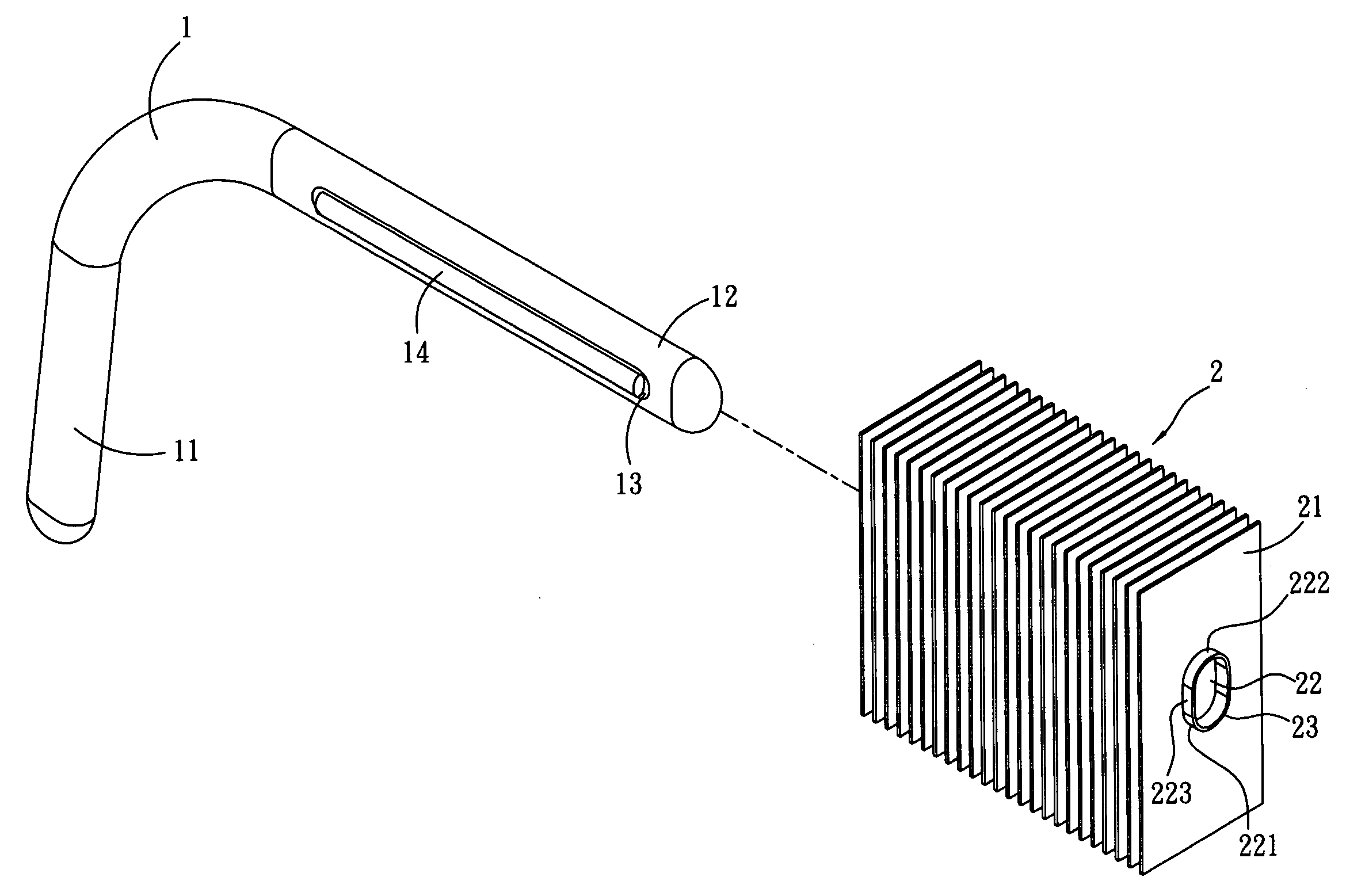
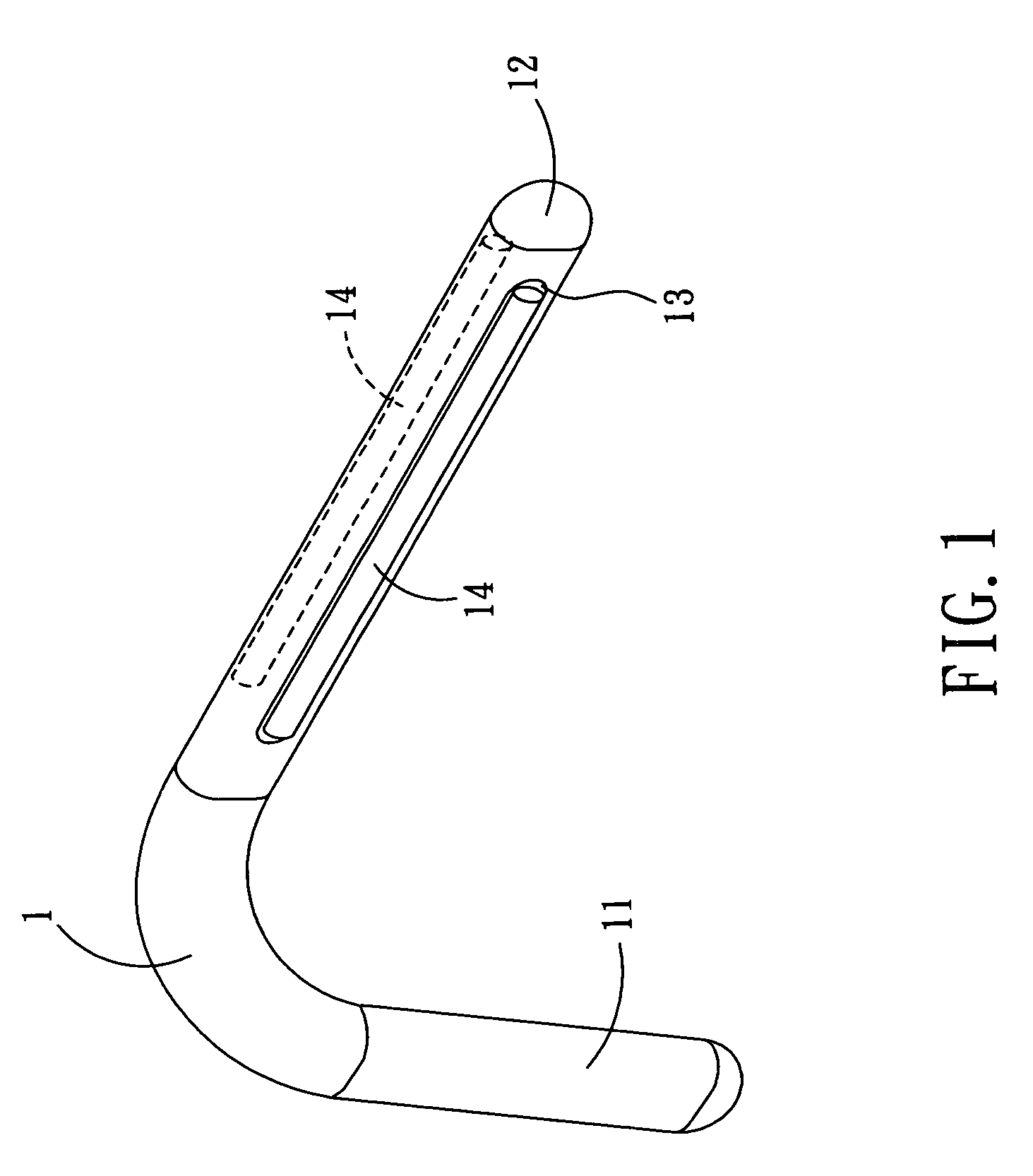
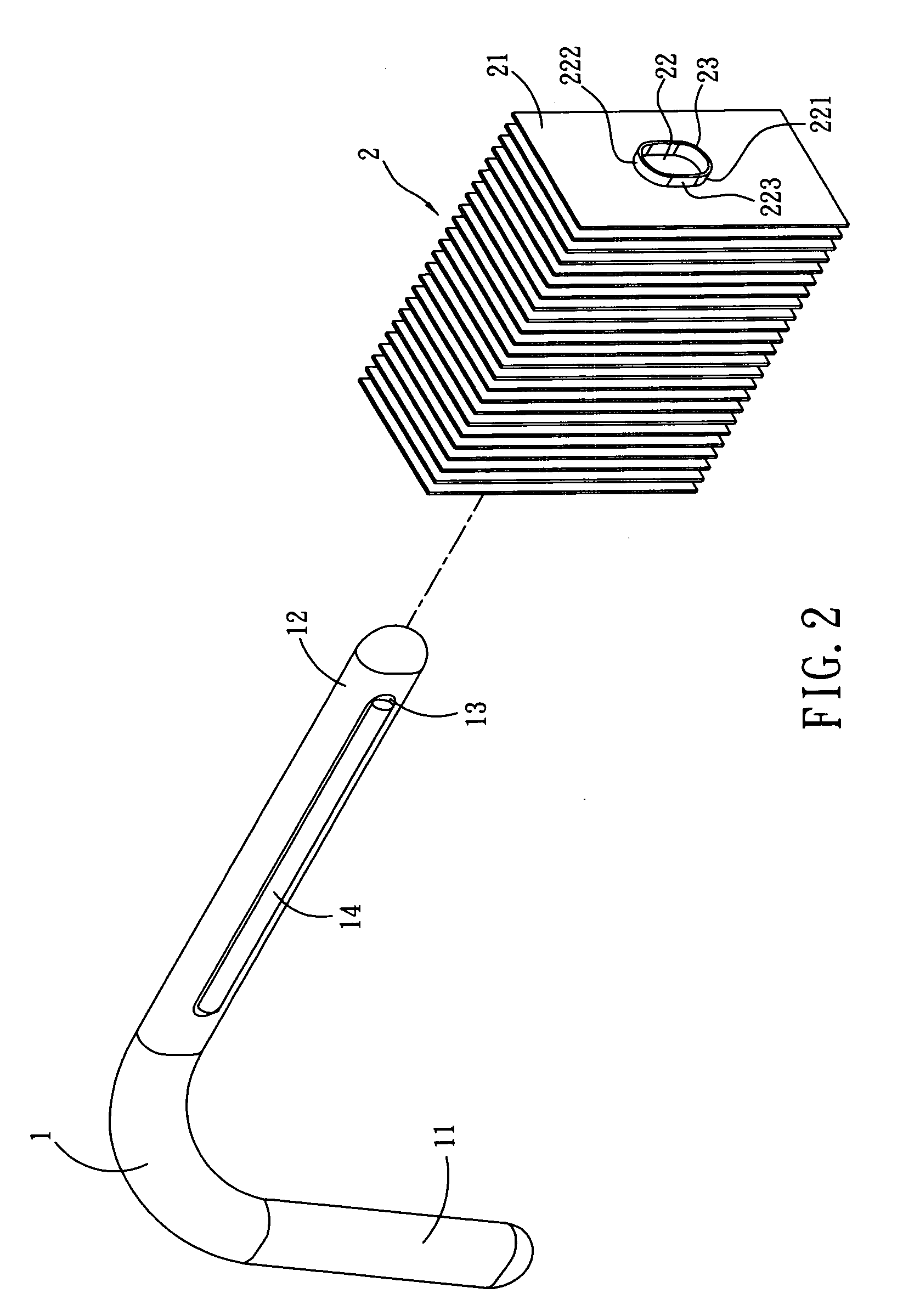
[0014]Referring to FIGS. 1 and 2, the structure of the present invention is illustrated. The present invention has the following components.

[0015]A heat tube 1 is coated with tin glue 14 which is well controlled so as to be well assembled to the fin set 2. One end of the heat tube 1 is a heated end 11 and another end thereof is a cooling end 12. Each of two sides of the cooling end 12 is formed with a plane 13. Each plane 13 is coated with tin glue 14.

[0016]A fin set 2 is formed by a plurality of fins 21. Each fin 21 is formed with an elliptical t...


PUM

PropertyMeasurementUnit
shapeaaaaaaaaaa
elliptical shapeaaaaaaaaaa
heataaaaaaaaaa

Abstract

A heat dissipating device comprises a heat tube; one end of the heat tube being a heated end and another end thereof being a cooling end; at least one side of the cooling end being formed with a plane; each plane being coated with tin glue; and a fin set being formed by a plurality of fins; each fin being formed with a through hole; each through hole having an upper cambered edge, a lower cambered edge, a left side, and a right side; the left and right edges being as correcting edges; one side of the through hole being formed with a flange. In assembly; the plane of the cooling end of the heat tube is coated with tin glue. The cooling end of the heat tube is inserted into the through holes of the fins of the fin set; and the upper and lower edges of the through holes have the effect of correcting the heat tube.

Description

FIELD OF THE INVENTION[0001]The present invention relates to heat dissipating devices, and in particular to a heat dissipating device with a heat tube and a fin set.BACKGROUND OF THE INVENTION[0002]Currently, a plurality of fins are installed to a cooling end of a heat tube. The heated end of the heat tube is assembled with a heat guide block which can be adhered to a surface of a heat source (such as a microprocessor). Thereby heat from the heat source is transferred through the heat guide block, heated end, cooling end to the fin set. Thereby heat can be dissipated effectively.[0003]When above mentioned fin set is combined to the heat tube, each fin of the fin set is formed with a through hole 22. An edge of the through hole is formed with a round hole which is communicated to the through hole. One side of the through hole is formed with a flange which has a shape identical to the through hole. After the cooling end of the heat tube is assembled to the through hole of each fin, a ...

Claims


Application Information

Patent Timeline
Patent Type & Authority Applications(United States)
IPC IPC(8): H05K7/20
CPCF28D15/0266F28F1/02F28F1/24F28F2275/025H01L23/427H01L2924/0002F28D15/0275H01L2924/00
Inventor SUNG, MIN-HSIEN
Owner SUNG MIN HSIEN
Why Eureka
Try Eureka