Magnetically induced aircraft landing wheel rotation

a technology of aircraft landing wheel and magnetic induction, which is applied in the direction of wheel arrangement, electrical apparatus, dynamo-electric machines, etc., can solve the problems of increasing brake load, little or no free space, and affecting the operation of aircraft landing wheel, so as to reduce tire wear and impact load, and convenient to use

Active Publication Date: 2007-12-13
SODERBERG ROD F
View PDF10 Cites 28 Cited by
  • Summary
  • Abstract
  • Description
  • Claims
  • Application Information

AI Technical Summary

Problems solved by technology

It is clearly seen that there is extremely little free space in any of the main landing wheel assembly, incorporating a brake stack within the wheel along with the brake actuating mechanism and wheel support structure leave little or no free space for mounting a small proprietary electric motor.
Few if any of the inventions associated with the prior art address what is claimed to be a significant problem associated with pre-rotation of aircraft landing wheels, this being either increased landing distance or increased brake loadings due to the loss of an amount of retardation energy that would otherwise be applied to the aircraft as a result of the energy dissipated during tire skidding and momentum transferred to achieve wheel rotation upon touch down.

Method used


Image

  • Magnetically induced aircraft landing wheel rotation
  • Magnetically induced aircraft landing wheel rotation
  • Magnetically induced aircraft landing wheel rotation

Examples


Embodiment Construction

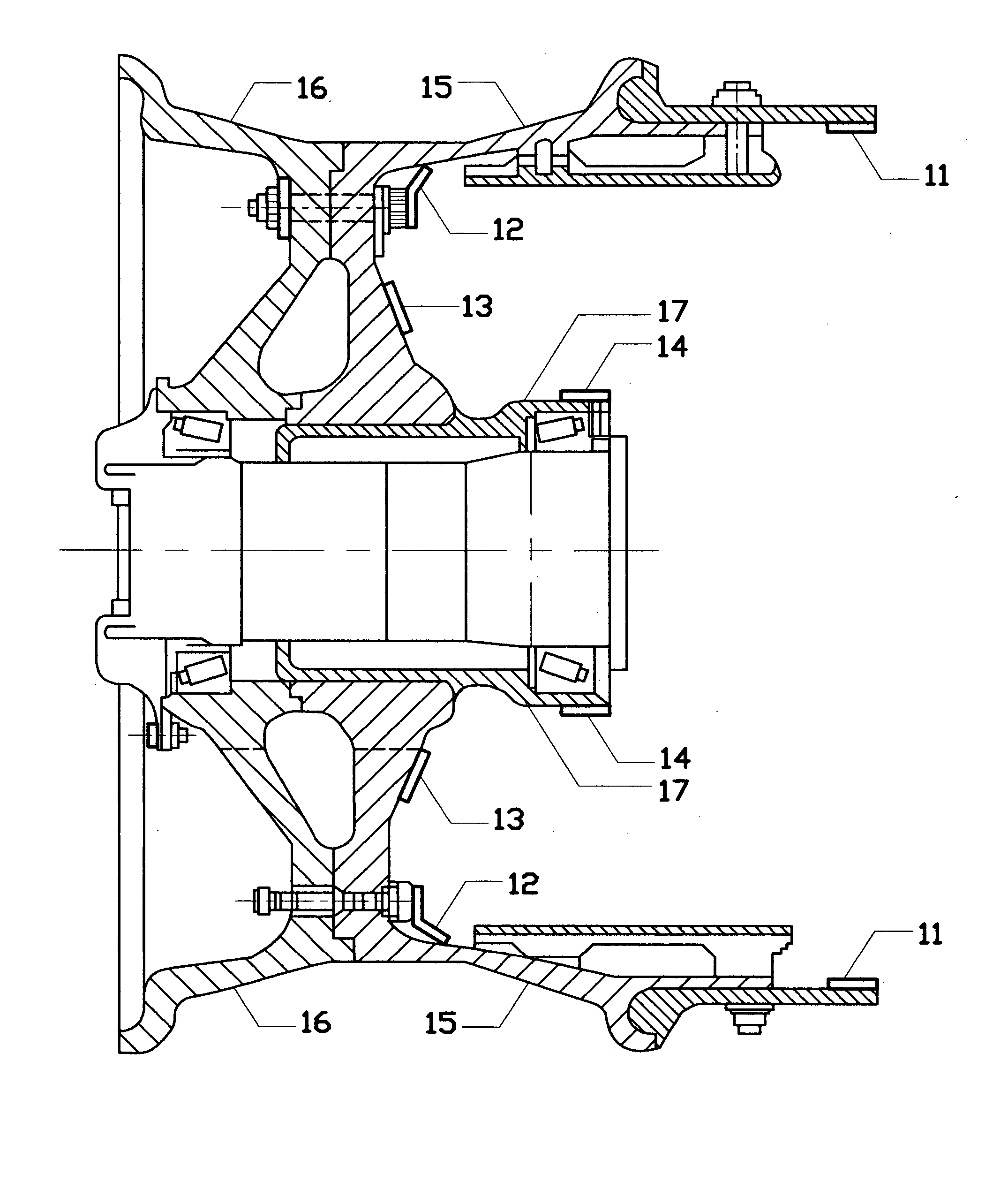
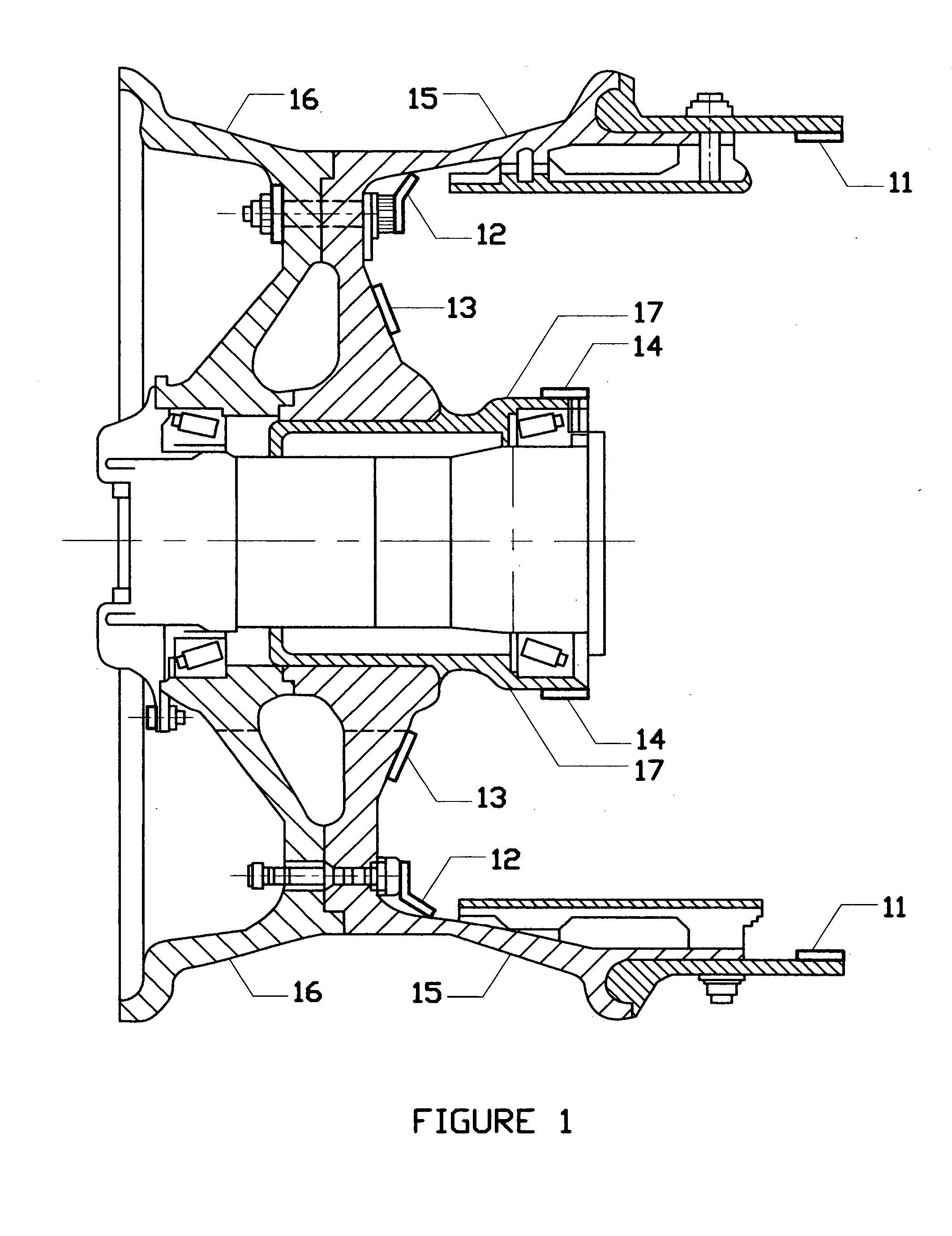
[0046] The present invention relates to improvements in aircraft landing wheel assembly. These improvements relate specifically to controlling the forward rolling speed of the wheel and tire assembly prior to landing and where required applying added retardation to the wheel after landing.

[0047] The aim is to adjust the wheel and tire assemblies forward rotational speed prior to landing so as to reduce tire skidding, reduce impact loading on the landing gear, reduce tire wear, thus reducing the chance of sudden tire failure and reducing impact wear and tear on wheels and landing gear. Safety is potentially improved and maintenance costs reduced.

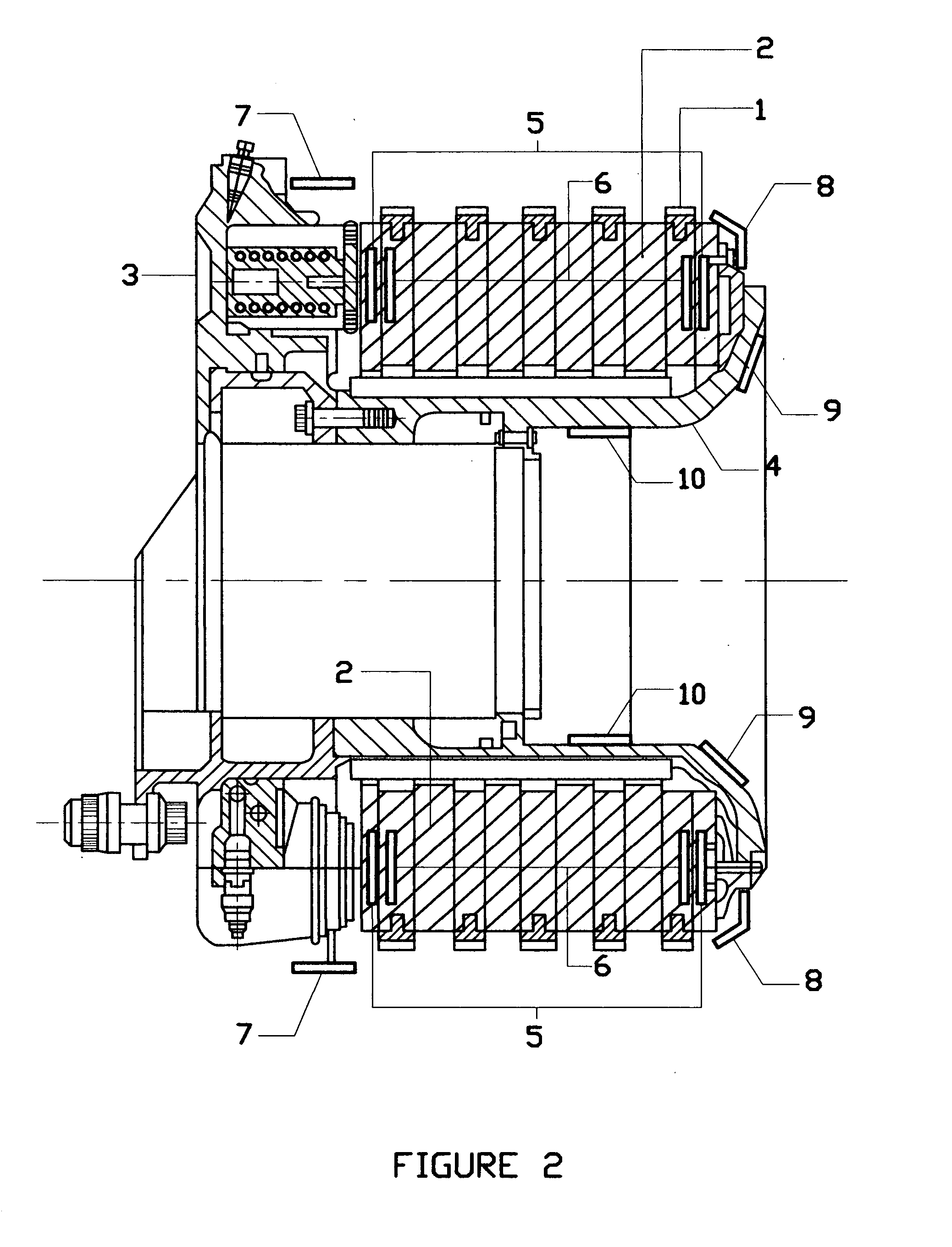
[0048] The objective of the system is to precisely control the forward rotational speed of the aircraft landing wheel-tire in relation to the ground speed just prior to landing and applying a degree of retardation assistance after touch down by means of an imposed electric current specifically to induce magnetic field forces located on or w...


PUM


Abstract

An aircraft landing wheel assembly comprising a set of rotating components and a set of static components wherein an applied electrical current applied to conductive elements associated with one set of components gives rise to primary magnetic fields which interact with reactive magnetic fields associated with the other set of components whereby the interaction of magnetic field forces gives rise to rotational forces which act on the rotating components of said aircraft landing wheel assembly to induce controlled forward rotation of the landing wheel prior to contact with the runway and controlled retardation assistance as required during deceleration of the aircraft after touch down with the runway.

Description

[0001] An Information Disclosure Statement is enclosed along with a full description of Prior Australian and P.C.T. Patent Applications by the Inventor of this present Invention.BACKGROUND OF THE INVENTION [0002] 1. Field of the Invention [0003] The present invention relates to an aircraft landing wheel rotating apparatus specifically designed to achieve controlled forward rotation of the main landing wheels of large commercial, and cargo aircraft prior to touch down with the runway thereby reducing wear on tires reducing impact loadings on the landing wheel assembly, reducing the possibility of sudden tire blowout. Improving aircraft stability at touch down by reducing differential torque reaction due to the fact that not all wheels impact the runway together and potentially improving brake efficiency by providing the option of a degree of retardation assistance after touch down during the deceleration of the aircraft while braking [0004] 2. Description of the Prior Art [0005] Airc...

Claims


Application Information

Patent Timeline
Patent Type & Authority Applications(United States)
IPC IPC(8): B64C25/00
CPCB64C25/36B64C25/405B64C25/42H02K3/02Y02T50/823H02K7/14H02K21/22H02K49/00H02K7/102Y02T50/80
Inventor SODERBERG, ROD F.
Owner SODERBERG ROD F
Why Eureka
Try Eureka