

Device for Displacing a Tongue Blade in Addition to a Height-Adjustable Roller Device
- Summary
- Abstract
- Description
- Claims
- Application Information
AI Technical Summary
Benefits of technology
Problems solved by technology
Method used
Image

Examples
first embodiment
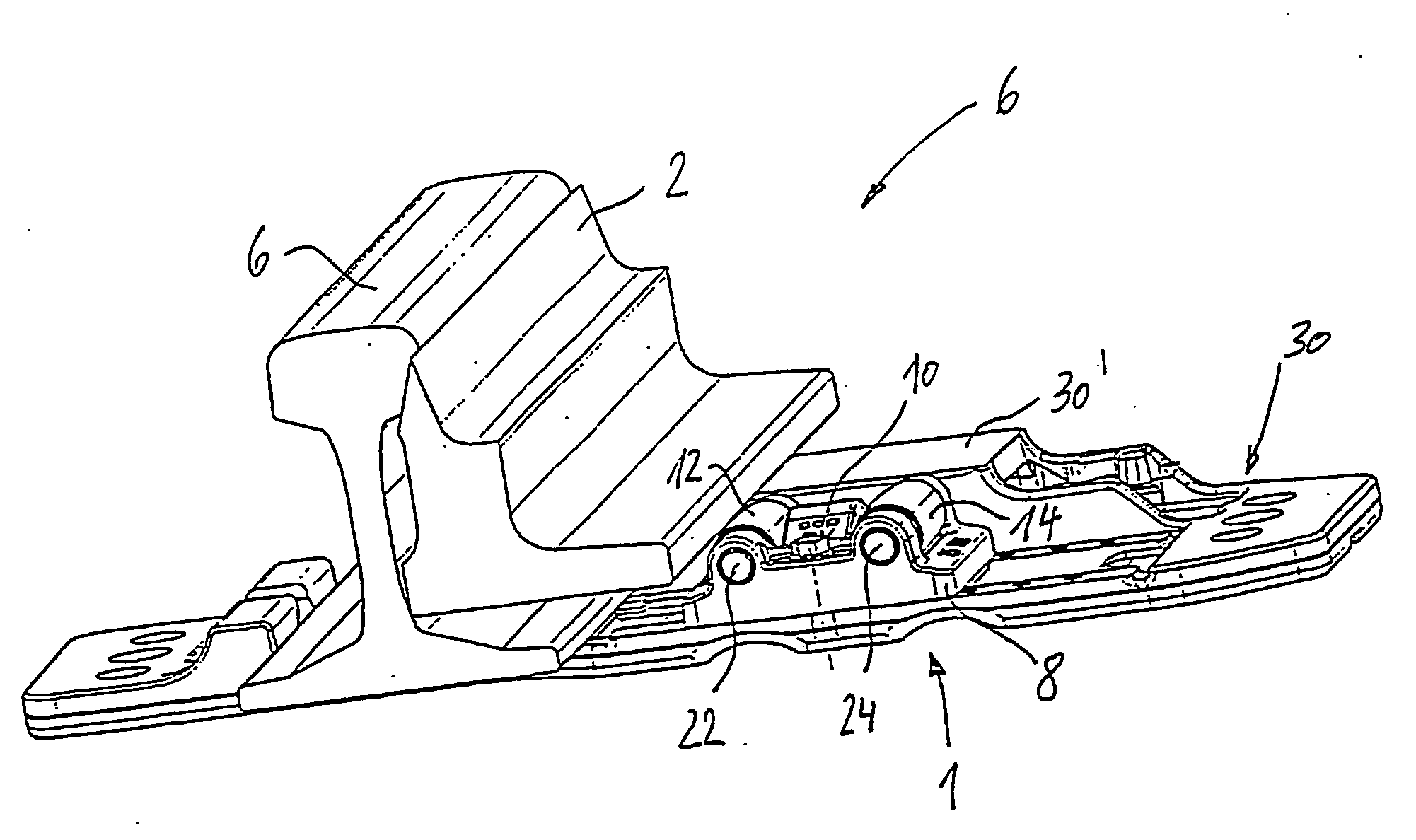
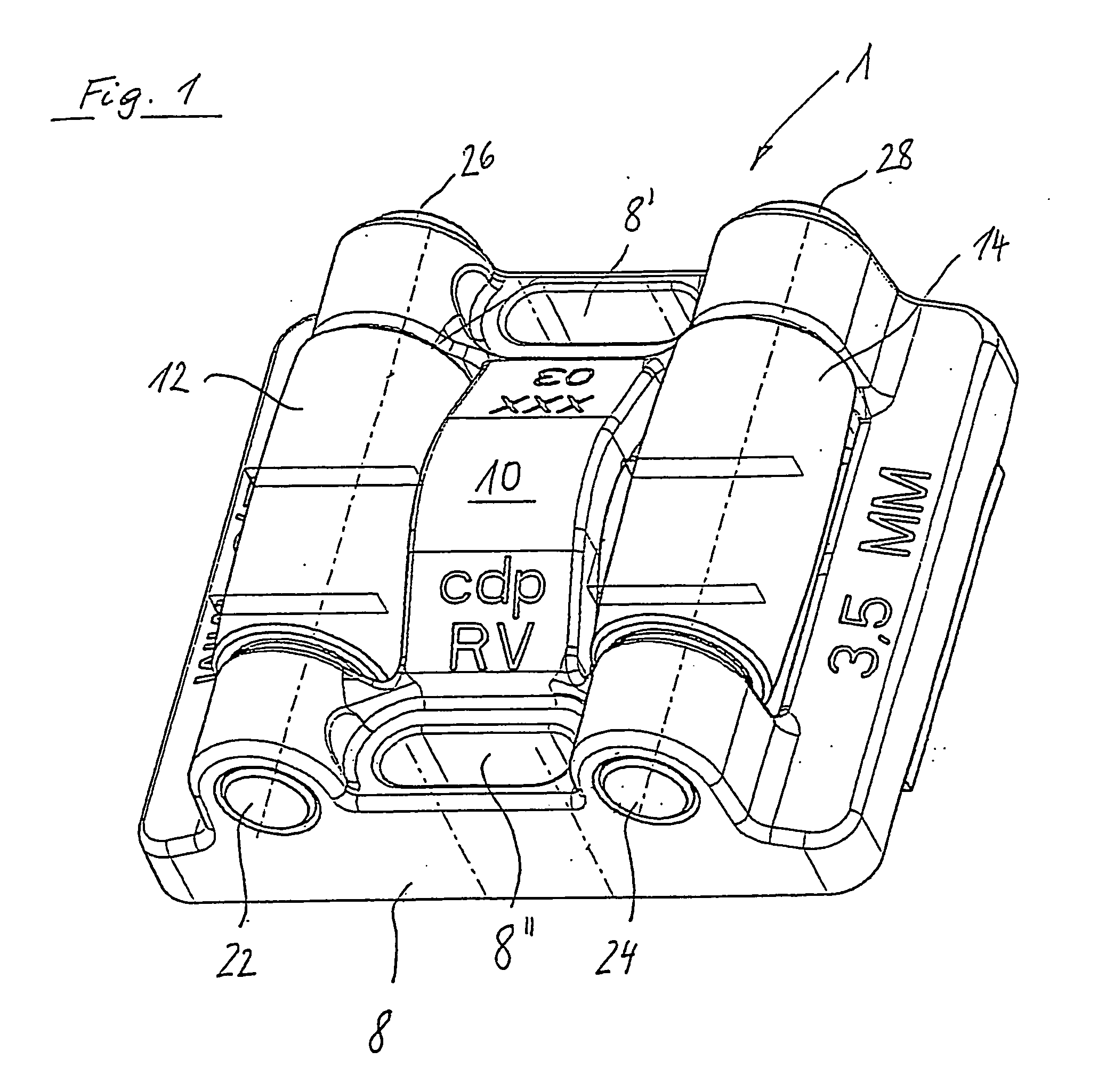
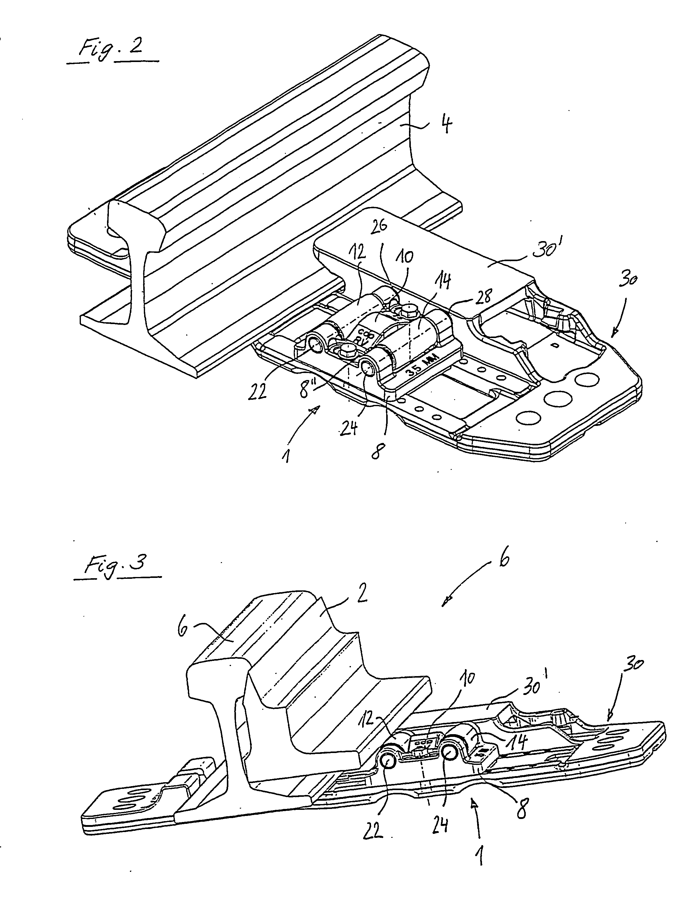
[0030]FIG. 1 shows a schematic perspective view of a tongue lifting device 1 as first embodiment of the present invention. Tongue lifting device 1 has a base body 8, in which two support carrier pins 22, 24 are supported. Support carrier pins 22, 24 serve to pivotably support one roller 12, 14 respectively in tongue lifting device 1. In addition base body 8 has two fixing apertures 8′, 8″, to fix tongue lifting device 1 in its installation position.
[0031] The first embodiment shown in FIG. 1 has two rollers 12, 14. However, it should be noted that three or even more rollers may be provided depending on the prevailing requirements, for example the required positioning range.
[0032] Between two adjacent rollers 12, 14 is provided a covering 10 which is oriented towards a first direction whereby the first direction in the present embodiment extends vertically upwards. The covering is designed such that it at least partially covers a passage present between two adjacent rollers 12, 14. ...
third embodiment
[0042]FIG. 7 shows tongue lifting device 1 according to the invention in which base body 8 also comprises a top section 8B and a bottom section 8A. The joining surfaces of both sections 8A, 8B are provided with a continuous slanted plane which runs at an angle in relation to the plane spanned by the underside of bottom section 8A. Height adjustment of top section 8B in relation to bottom section 8A takes place in this case too by displacing top section 8B in the direction or opposing direction of arrow B from FIG. 7. In addition, a threaded rod 32 which ends outside base body 8 in a hexagon head 33 is connected to top section 8B and bottom section 8A. A tool (not shown) attached to this hexagon head 33 can apply a torque to threaded rod 32 and thus bring about stepless displacement of top section 8B on bottom section 8A.
PUM
 Abstract
Description
Claims
Application Information