Aircraft electric brake and generator therefor

a technology of electric brakes and generators, applied in the direction of braking systems, aircraft braking arrangements, transportation and packaging, etc., can solve the problem of not always possible or practical to run high-voltage power along the landing gear stru

Inactive Publication Date: 2007-12-13
HONEYWELL INT INC
View PDF27 Cites 58 Cited by
  • Summary
  • Abstract
  • Description
  • Claims
  • Application Information

AI Technical Summary

Problems solved by technology

However, for safety reasons, which may be the subject of government regulations, for example, it is not always possible or practical to run high-voltage power along a landing gear strut to the brakes.

Method used


Image

  • Aircraft electric brake and generator therefor
  • Aircraft electric brake and generator therefor
  • Aircraft electric brake and generator therefor

Examples


Embodiment Construction

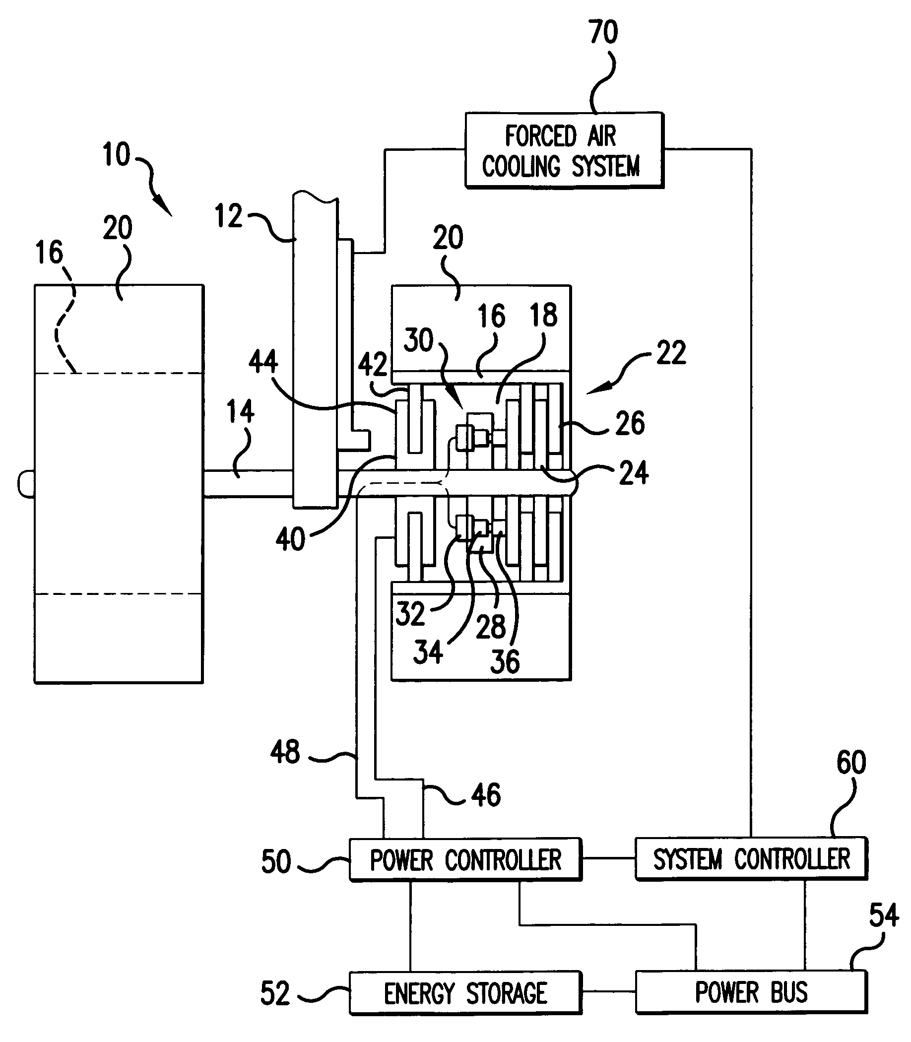
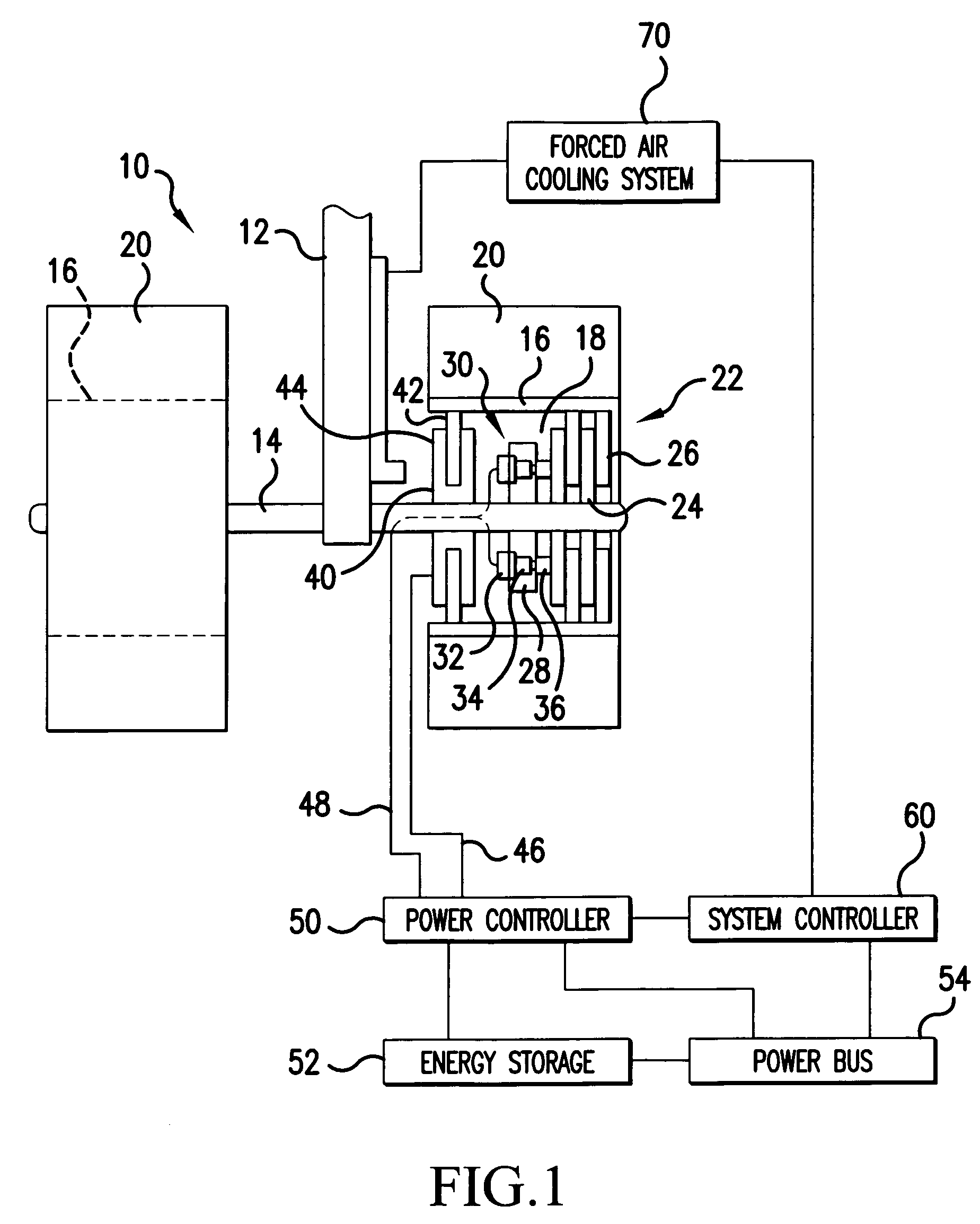
[0014]Referring now to the drawings, wherein the showings are for the purpose of illustrating preferred embodiments of the invention only and not for the purpose of limiting same, FIG. 1 schematically illustrates an aircraft landing gear system 10 that includes a strut 12, an axle 14 connected to strut 12, first and second wheels 16 having interiors 18, mounted for rotation about axle 14, and first and second tires 20 mounted on wheels 16. A brake stack 22 is provided in one or each wheel interior 18 and includes a plurality of stators 24 fixed to axle 14 and a plurality of rotors 26 connected to wheel 16 for rotation therewith between pairs of stators 24. An actuator ring 28 is mounted on axle 14 and supports a plurality of electromechanical actuators 30, each of which comprises an electric motor 32, a ballnut / ballscrew assembly 34 and a piston 36.

[0015]A generator 40 is also mounted in wheel interior 18 and includes a generator rotor 42 connectable to wheel 16 for rotation therewi...


PUM


Abstract

An aircraft braking system includes a brake disk stack (22) that has at least one brake rotor (26) rotatable with an aircraft wheel (16) and at least one brake stator (24), at least one actuator (36) movable in response to a braking command to compress the brake disk stack (22) and slow the wheel (16), at least one actuator motor (32) operably connected to the at least one actuator (36) for moving the at least one actuator (36), a generator (40, 82, 100) having a generator rotor (42) and a generator stator (44), the generator (40, 82, 100) being operably connectable to the aircraft wheel (16) such that said generator rotor (42) rotates when the wheel (16) rotates, and a controller (50) electrically connected to the generator (40, 82, 100) and the at least one actuator motor (32). Also a method of generating electrical power from an aircraft wheel (16).

Description

FIELD OF THE INVENTION[0001]The present invention is directed to an aircraft electric brake and a generator for powering the electric brake, and to a method of using same, and, more specifically, toward an aircraft electric brake powered by a generator having a generator rotor operably connectable to an aircraft wheel whereby rotation of the wheel rotates the generator rotor and produces power for the electric brake, and to a method of using the generator.BACKGROUND OF THE INVENTION[0002]Aircraft brakes often include one or more rotors that rotate with an aircraft wheel and stators fixed with respect to aircraft landing gear which extend between the rotors. The rotors and stators are arranged in an alternating manner to form a brake disk stack and are normally spaced so that the aircraft wheel can rotate freely. When the disk stack is compressed, the rotors and stators are forced into contact which produces friction to slow and stop the wheel.[0003]Various actuators are known for ap...

Claims


Application Information

Patent Timeline
Patent Type & Authority Applications(United States)
IPC IPC(8): B60T8/64
CPCB60K6/48B60T1/10B60T13/746B64C25/405Y02T50/823B64C25/44F16D61/00F16D2121/24Y02T10/6221B64C25/42Y02T10/62Y02T50/80
Inventor CHARLES, DAVID L.BEEHLER, JONATHAN T.KESSINGER, ROY LEEDEMPSTER, JOHN BRIAN
Owner HONEYWELL INT INC
Why Eureka
Try Eureka