Light source device and image displaying apparatus using the same

Active Publication Date: 2007-12-13
RAKUTEN GRP INC
View PDF6 Cites 6 Cited by
  • Summary
  • Abstract
  • Description
  • Claims
  • Application Information

AI Technical Summary

Benefits of technology

[0012] The present invention has been made in consideration of the foregoing difficulties, and an object of the present invention is to provide a light source device of which light condensing efficiency is made higher by reducing the “etendue” of the light so

Problems solved by technology

Hence even if the light condensing system employs the convex lens system, a light condensing efficiency is low and unsatisfactory, because a flux of light passing a comparatively narrow angular range next to the light axis is utilized as light traveling

Method used


Image

  • Light source device and image displaying apparatus using the same
  • Light source device and image displaying apparatus using the same
  • Light source device and image displaying apparatus using the same

Examples


first embodiment

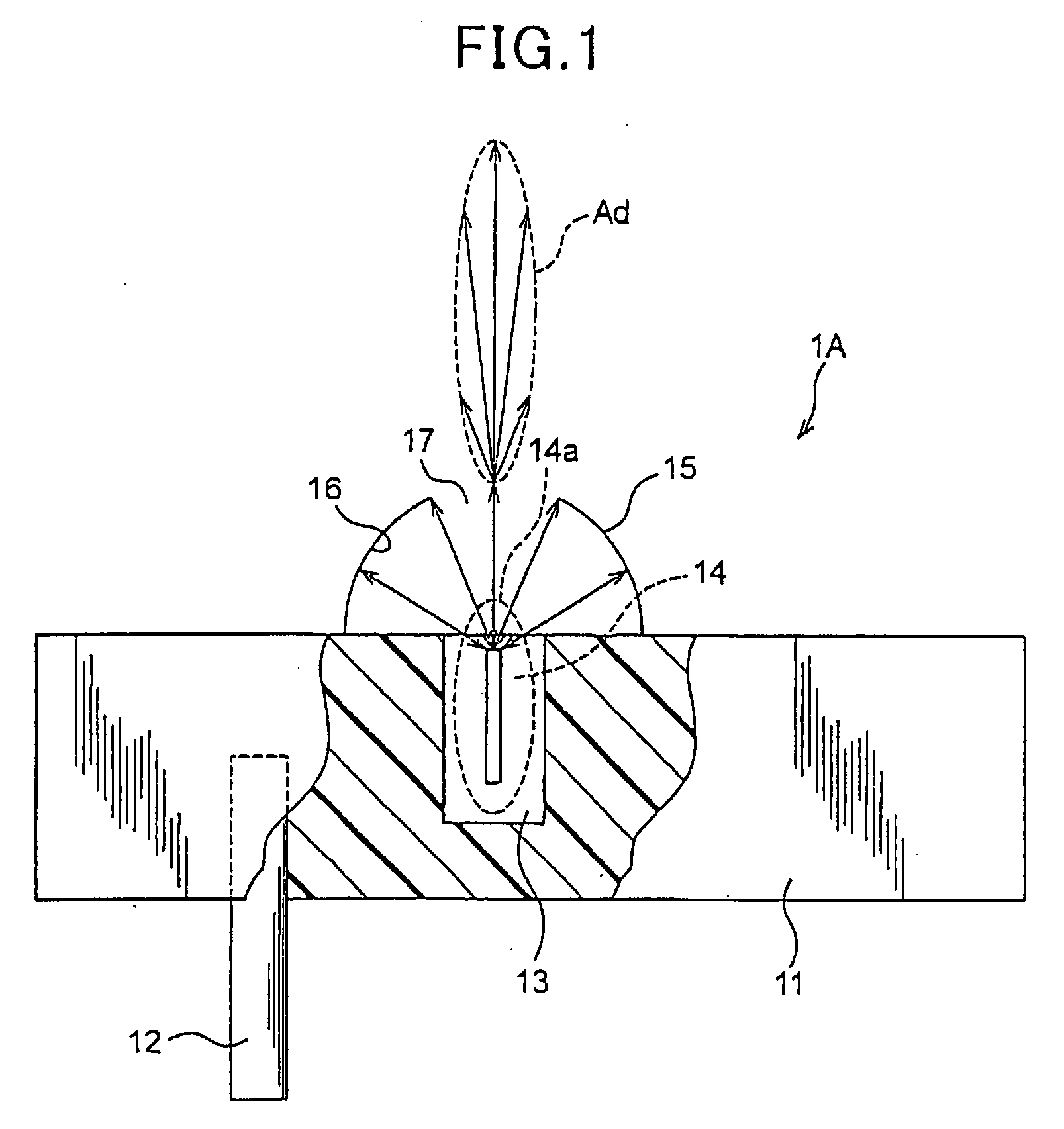
[0030] Referring to FIG. 1, a first embodiment of the light source device according to the present invention will now be described.

[0031] As shown in FIG. 1, a light source device 1A of the present embodiment is provided with a waveguide 11, a probe 12, an electrodeless lamp 14, and a spherical reflecting mirror 15. Of these, the waveguide 11 is a cylindrical member made of a dielectric material with an outer surface coated with a metal material. The waveguide 11 has a central axis along an axial direction and both circular end surfaces in the axial direction. At a part of one of both axial end surfaces, which part is located at the center or near the center thereof, an aperture cavity 13 is formed to open outside.

[0032] The electrodeless lamp 14 is a lamp emitting light in response to applying microwaves thereto and is formed to have a thin and long shape having a longitudinal direction. This electrodeless lamp 14 is loaded in the aperture cavity 13 such that one end of this elec...

second embodiment

[0038] Referring to FIG. 2, a second embodiment of the present invention will now be described. In the present embodiment and subsequent embodiments, for the sake of removing redundancy of the description, components identical or similar to those described in the previous embodiments will be given the same reference numerals and the explanations therefore will be omitted or simplified.

[0039] In the present embodiment, the light source device is reduced Into practice in another form.

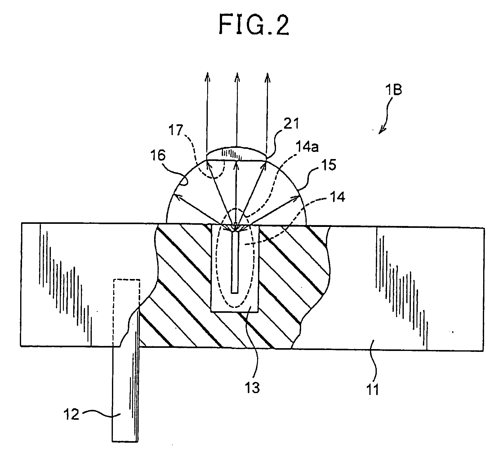
[0040]FIG. 2 shows the structure of a light source device 1B according to the present embodiment. As shown therein, the light source device 1B is additionally provided with a convex lens 21 mounted on the spherical reflecting mirror 15 to cover the aperture 17 thereof. The remaining components of this device 1B are identical to those in FIG. 1 explaining the first embodiment.

[0041] Accordingly, the flux of light radiated through the aperture 17 of the spherical reflecting mirror 15 is collimated into a...

third embodiment

[0043] Referring to FIG. 3, a second embodiment of the present invention will now be described. In the present embodiment, the light source device is reduced into practice in another form.

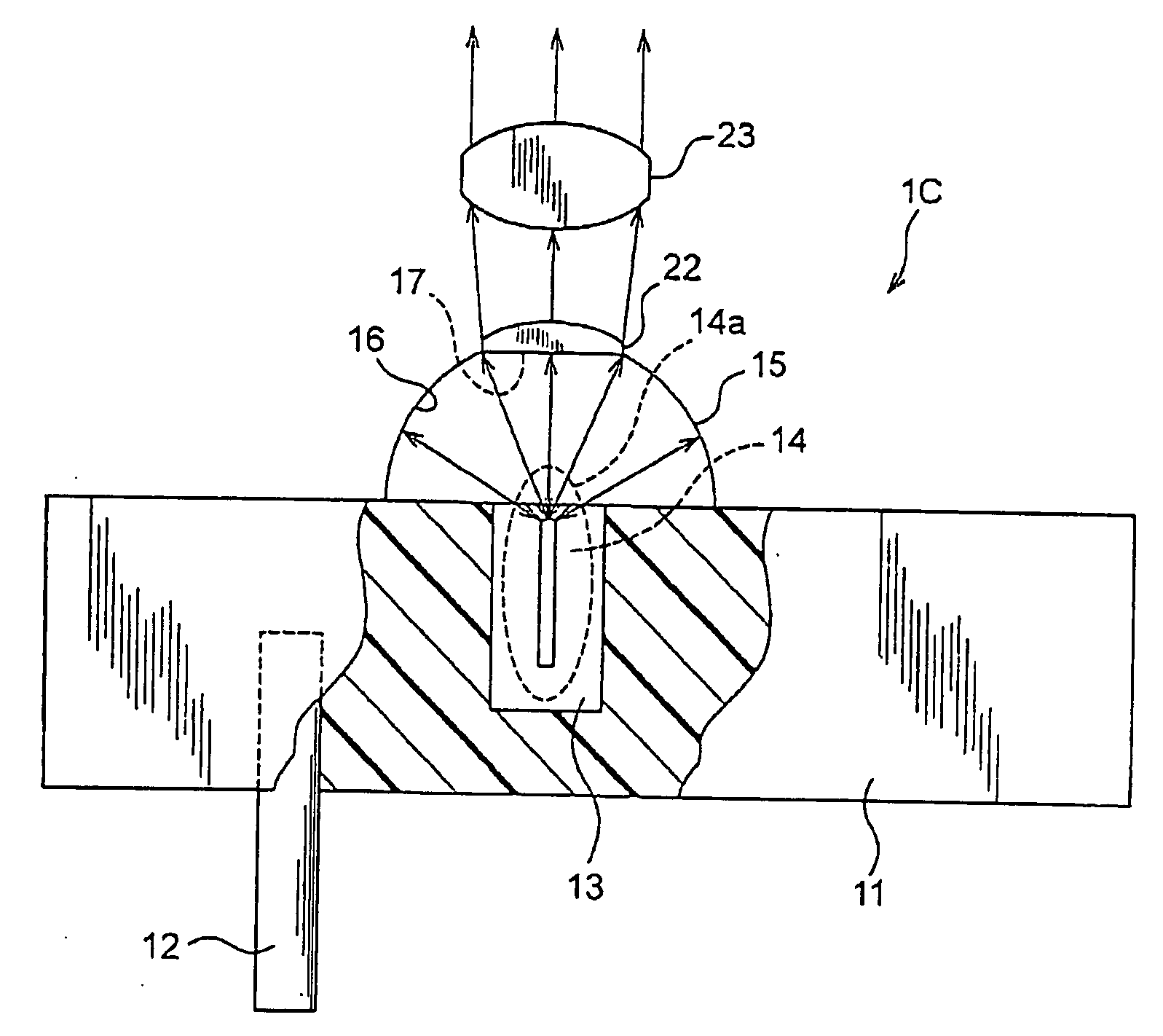
[0044]FIG. 3 shows the structure of a light source device 1C according to the present embodiment. As shown therein, the light source device 1C is additionally provided with a lens system consisting of convex lenses 22 and 23. Of these, the convex lens 22 is mounted on the spherical reflecting mirror 15 to cover the aperture 17 thereof, while the convex lens 23 is fixedly located apart from the convex lens 22 by a predetermined distance in front of the convex lens 22. The remaining components of this device 1C are identical to those in FIG. 1 explaining the first embodiment.

[0045] Hence the flux of light radiated through the aperture 17 of the spherical reflecting mirror 15 is narrowed in its radiation angle by the first convex lens 22, and then collimated by the second convex lens 23. Accordingly...


PUM


Abstract

A light source device comprises a waveguide, an electrodeless lamp, a probe, and conversing means. The waveguide is formed to contain a medium enabling a microwave to resonate and has a surface and an aperture cavity with an aperture opened at a predetermined position of the surface. The electrodeless lamp is loaded in the aperture cavity in a state where part of the electrodeless lamp is protruded from the surface of the waveguide so that the part of the electrode lamp emits light in response to applying the microwave to the electrodeless lamp. The probe supplies a high-frequency signal to the waveguide so that the high-frequency signal is converted to the microwave in the waveguide. The converging means is disposed on the surface of the waveguide to face the aperture cavity and utilizes all the light emitted from the part of the electrodeless lamp to converge the light.

Description

CROSS REFERENCE TO RELATED APPLICATION [0001] Japanese Patent applications No. 2006-161481 filed on Jun. 9, 2006 and No. 2006-161486 filed on Jun. 9, 2006. BACKGROUND OF THE INVENTION [0002] 1. Field of the Invention [0003] The present invention relates to a light source device and an image displaying apparatus, and in particular, to a light source device comprising a waveguide and an electrodeless lamp loaded in an aperture cavity formed in the waveguide such that the electrodeless lamp emits light in response to microwaves generated in the waveguide, and to an image displaying apparatus that employs such a light source device. [0004] 2. Description of the Related Art [0005] A light source device has been known which comprises a waveguide and an electrodeless lamp, in which the electrodeless lamp is arranged in the waveguide to emit light. Such light source devices are disclosed by U.S. Pat. No. 6,737,809, for example. [0006] Specifically, the above patent discloses a light source ...

Claims


Application Information

Patent Timeline
IPC IPC(8): H03H9/00
CPCG03B21/2026G03B21/2006G03B21/208
Inventor TAKAHASHI, RYUSAKU
Owner RAKUTEN GRP INC
Why Eureka
Try Eureka