Liquid ejecting head and liquid ejecting apparatus

a liquid ejecting head and liquid ejecting technology, which is applied in the direction of printing, inking apparatus, etc., can solve the problems of defective connection, increase in head size, increase manufacturing cost, etc., and achieve the effect of enhancing the reliability of the head and promoting the reduction of the head siz

Active Publication Date: 2007-12-13
SEIKO EPSON CORP
View PDF3 Cites 16 Cited by
  • Summary
  • Abstract
  • Description
  • Claims
  • Application Information

AI Technical Summary

Benefits of technology

[0022]With this configuration, a liquid ejecting apparatus can be provided that is capable of promoting the reduction in size of the head, and enhancing the reliability of the head.

Problems solved by technology

This may increase manufacturing cost, and cause the adjacent wires to short-circuit, resulting in occurrence of defective connection.
This may cause an increase in size of the head.
These problems may be involved not only in the ink jet recording heads that eject ink, but also in other liquid ejecting heads that eject liquid other than ink.
Accordingly, even when the joint substrate for constituting the passage is bonded on the passage-forming substrate, a conductive adhesive used for mounting the IC chip may not have the ink-resistant characteristic.

Method used


Image

  • Liquid ejecting head and liquid ejecting apparatus
  • Liquid ejecting head and liquid ejecting apparatus
  • Liquid ejecting head and liquid ejecting apparatus

Examples


first embodiment

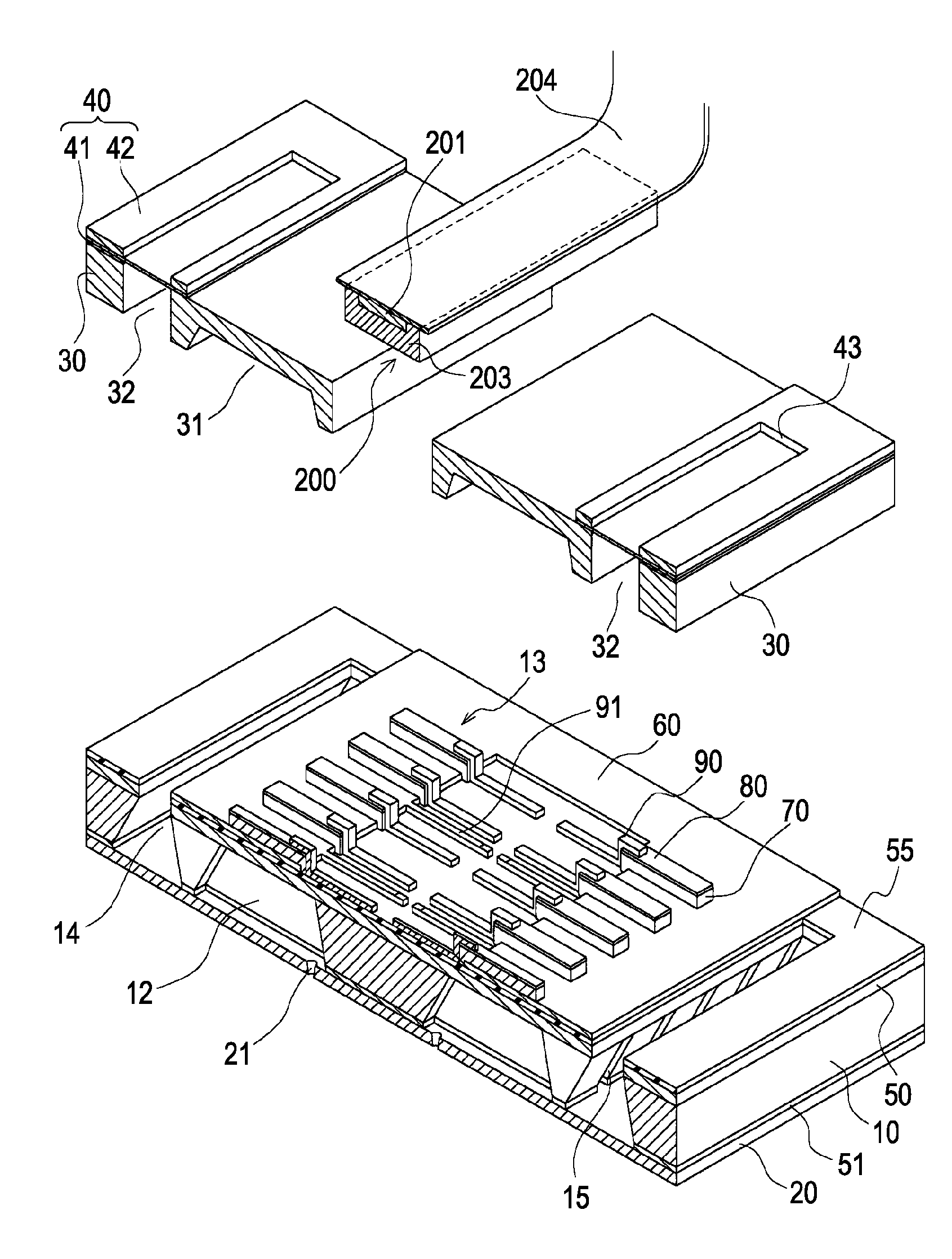
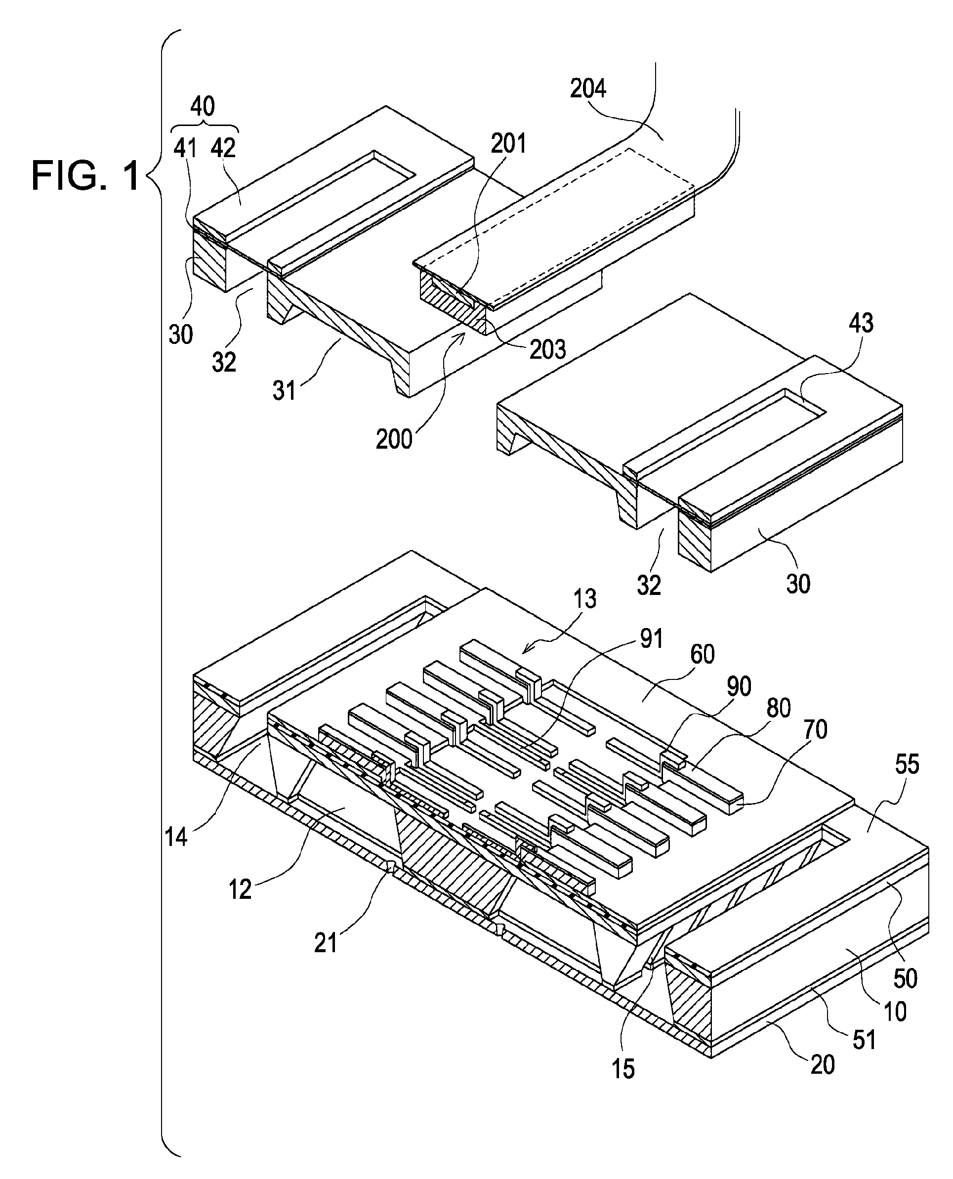
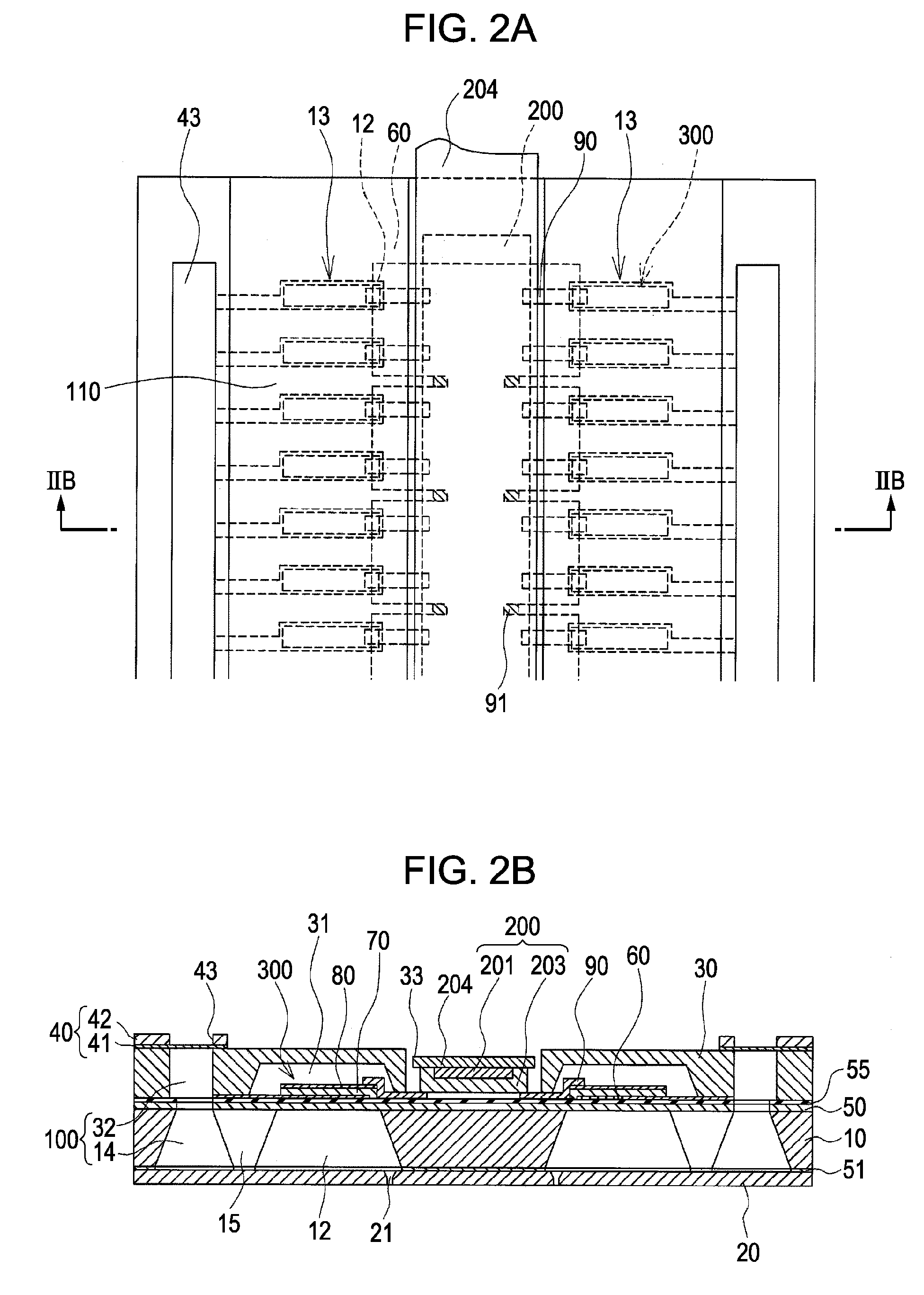
[0032]FIG. 1 is an exploded perspective view showing an ink jet recording head which is an example of a liquid ejecting head according to a first embodiment of the invention. FIGS. 2A and 2B are a plan view and a cross-sectional view of FIG. 1. As shown in the drawings, a passage-forming substrate 10 is made of a silicon single crystal substrate arranged along a plane (110) in this embodiment. An elastic film 50 is previously formed on one surface of the passage-forming substrate 10. The elastic film 50 has a thickness ranging from 0.5 to 2 μm and made of silicon dioxide by thermal oxidization. A plurality of pressure-generating chambers 12 are aligned in a width direction of the passage-forming substrate 10 to form an array 13. Here, two arrays 13 are provided at the passage-forming substrate 10. Communicating portions 14 are provided in regions of the passage-forming substrate 10 at outer sides in a longitudinal direction of the arrays 13 of the pressure-generating chambers 12. Th...

second embodiment

[0049]FIG. 4 is an enlarged cross-sectional view showing the overview of the ink jet recording head according to a second embodiment. This embodiment is a modification of the IC chip 200, and other components are similar to those of the first embodiment. In particular, as shown in FIG. 4, an IC chip 200A of this embodiment includes two laminated semiconductor substrates (a first semiconductor substrate 203A and a second semiconductor substrate 203B). The first and second semiconductor substrates 203A and 203B respectively have first and second through electrodes 202A and 202B. The first through electrodes 202A provided in the first semiconductor substrate 203A are connected to the second through electrodes 202B provided in the second semiconductor substrate 203B, via an intermediate wiring pattern 209 provided between the first and second semiconductor substrates 203A and 203B.

[0050]With this configuration, a connection portion where the through electrodes (first through electrodes)...


PUM


Abstract

A liquid ejecting head includes a passage-forming substrate, a plurality of pressure-generating elements, and an IC chip. The passage-forming substrate has a nozzle opening, and a pressure-generating chamber communicating with the nozzle opening. The plurality of pressure-generating elements are provided on a surface of the passage-forming substrate with a diaphragm interposed therebetween. The pressure-generating elements have electrodes and cause pressure change in the pressure-generating chamber. The IC chip is mounted on the surface of the passage-forming substrate with the pressure-generating elements. In this liquid ejecting head, the electrodes of the pressure-generating elements include individual electrodes, and at least the individual electrodes are electrically connected to the driver circuit via the through electrode.

Description

[0001]The entire disclosure of Japanese Patent Application No, 2006-162763, filed Jun. 12, 2006 is expressly incorporated by reference herein.BACKGROUND[0002]1. Technical Field[0003]The present invention generally relates to liquid ejecting heads and liquid ejecting apparatuses, and more particularly, it relates to an ink jet recording head and an ink jet recording apparatus in which a portion of a pressure-generating chamber communicating with a nozzle opening that ejects an ink droplet is constituted by a diaphragm, a piezoelectric element is provided on a surface of the diaphragm, and the ink droplet is ejected by displacement of the piezoelectric element.[0004]2. Related Art[0005]A typical ink jet recording head has a configuration in which a portion of a pressure-generating chamber communicating with a nozzle opening that ejects an ink droplet is constituted by a diaphragm, the diaphragm is deformed by a piezoelectric element to apply a pressure to ink provided in the pressure-...

Claims


Application Information

Patent Timeline
Patent Type & Authority Applications(United States)
IPC IPC(8): B41J2/05
CPCB41J2/14233B41J2002/14241B41J2202/18B41J2002/14491B41J2002/14419
Inventor KANAYA, MUNEHIDE
Owner SEIKO EPSON CORP
Why Eureka
Try Eureka