Catadioptric imaging system with beam splitter

Inactive Publication Date: 2007-12-13
CARL ZEISS SMT GMBH
View PDF13 Cites 4 Cited by
  • Summary
  • Abstract
  • Description
  • Claims
  • Application Information

AI Technical Summary

Benefits of technology

[0014] It is one object of the invention to provide a catadioptric imaging system capable of high image-side numerical aperture NA where a beam splitter with moderate size is used and where the angular load of radiation impinging on a beam split

Problems solved by technology

However, there are very few materials, in particular, synthetic quartz glass (fused silica) and crystalline fluorides, that are sufficiently transparent in that wavelength region available for fabricating the optical elements required.
Since the Abbe numbers of those materials that are available lie rather close to one another, it is difficult to provide purely refractive systems that are sufficiently well color-corrected (corrected for chromatic aberrations).
It has been pointed out that the most difficult requirement that one can ask of any optical design is that it has a flat image, especially if it is an all-refractive design.
Providing a flat image requires opposing lens powers and that leads to stronger lenses, more system length, larger system glass m

Method used


Image

  • Catadioptric imaging system with beam splitter
  • Catadioptric imaging system with beam splitter
  • Catadioptric imaging system with beam splitter

Examples


Example

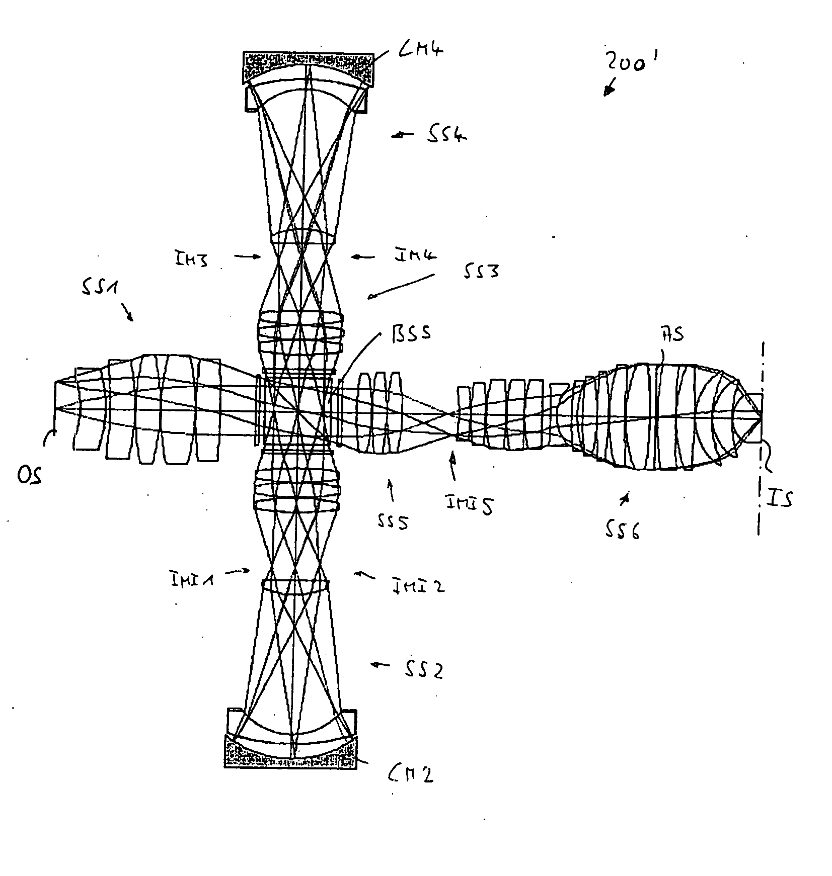
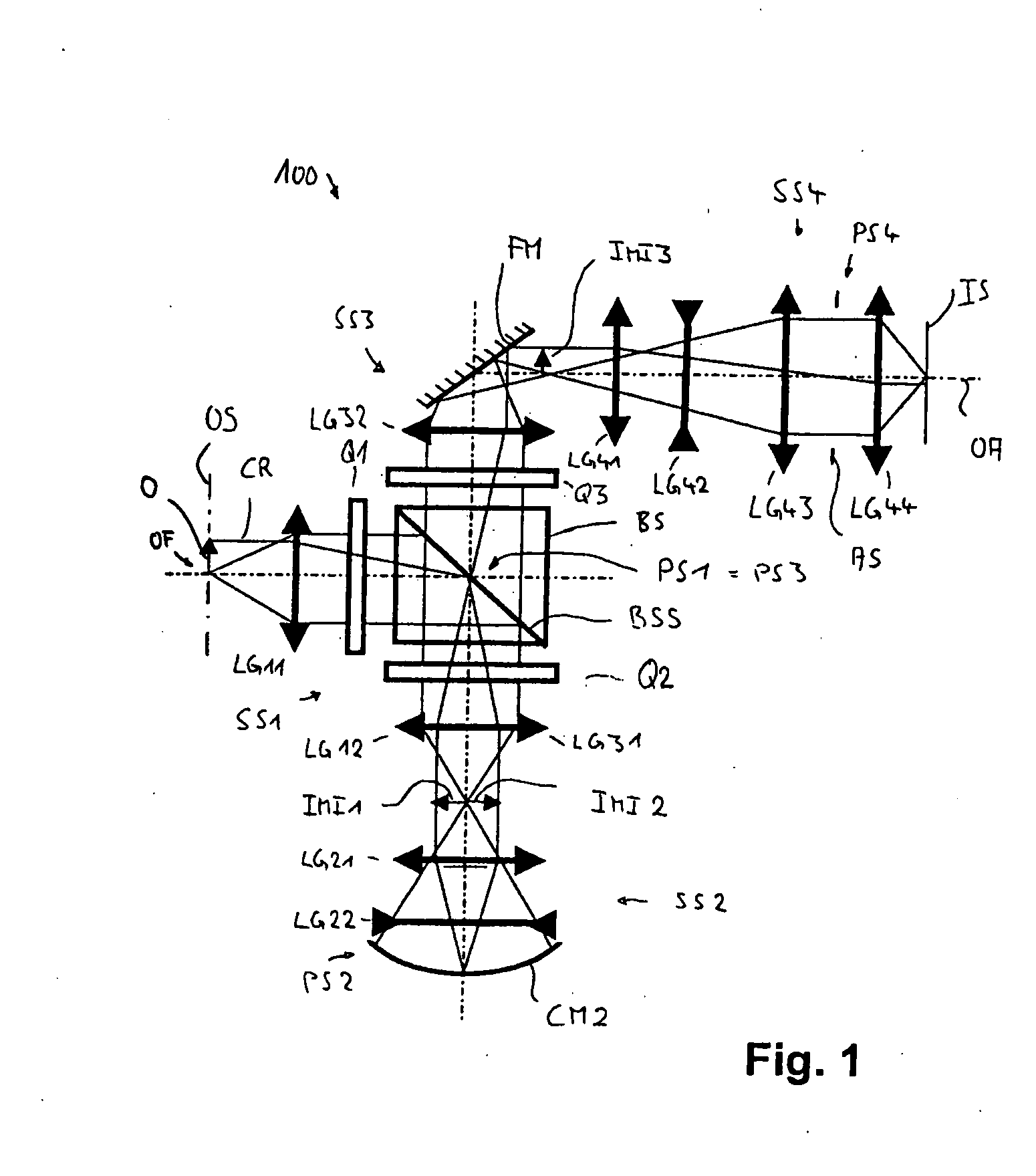
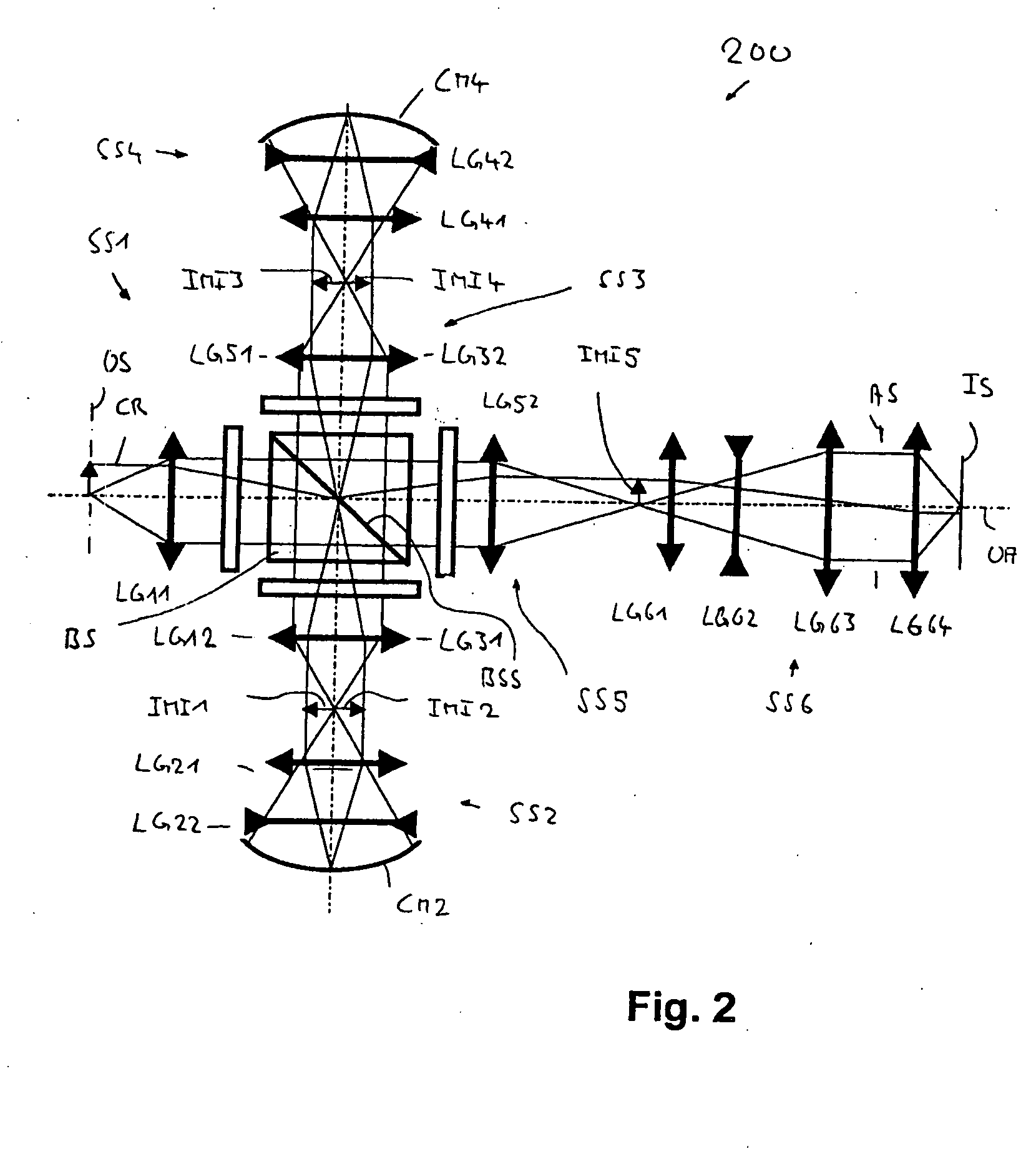
[0036] In the following description of preferred embodiments of the invention, the term “optical axis” shall refer to a straight line or sequence of straight-line segments passing through the centers of curvature of the optical elements involved. The optical axis is folded at planar mirror surfaces (e.g. at deflecting mirrors) or other reflective surfaces. In the case of those examples presented here, the object involved is either a mask (reticle) bearing the pattern of an integrated circuit or some other pattern, for example, a grating pattern. In the examples presented here, the image of the object is projected onto a wafer serving as a substrate that is coated with a layer of photoresist, although other types of substrates, such as components of liquid-crystal displays or substrates for optical gratings, are also feasible.

[0037] Concatenated imaging systems are described. The term “concatenated system” as used here refers to an imaging system that includes two or more imaging su...


PUM


Abstract

A catadioptric imaging system for imaging an on-axis object field arranged in an object surface of the imaging system onto an on-axis image field arranged in an image surface of the imaging system while creating at least one intermediate image has at least two imaging subsystems concatenated at an intermediate image such that the intermediate image formed by an imaging subsystem immediately upstream of that intermediate image forms the object of a subsequent imaging subsystem immediately downstream of that intermediate image. Each imaging subsystem includes a pupil surface and at least one of the imaging subsystems is a catadioptric or catoptric imaging subsystem including a concave mirror. The imaging system includes a geometric beam splitter having at least one planar beam splitter surface formed by a fully reflecting mirror, the beam splitter surface being arranged at or optically near to a pupil surface.

Description

[0001] This application claims priority from European Patent Application No. 06005813.8, filed Mar. 22, 2006, which is hereby incorporated by reference into the present application. BACKGROUND OF THE INVENTION [0002] 1. Field of the Invention [0003] The invention relates to a catadioptric imaging system for imaging an object field arranged in an object surface of the imaging system onto an image field arranged in an image surface of the imaging system while creating at least one intermediate image. In a preferred field of application the imaging system is designed as a catadioptric projection objective for a microlithographic projection exposure system designed for projection using radiation in the ultraviolet spectrum or as a partial system within such a projection objective. [0004] 2. Description of the Related Art [0005] Catadioptric projection objectives are, for example, employed in projection exposure systems, in particular wafer scanners or wafer steppers, used for fabricatin...

Claims


Application Information

Patent Timeline
IPC IPC(8): G02B17/08
CPCG02B17/08G03F7/70225G02B17/0892
Inventor DODOC, AURELIAN
Owner CARL ZEISS SMT GMBH
Why Eureka
Try Eureka