Acrobatic and gymnastic spotting apparatus

a technology for gymnastics and spotting equipment, applied in gymnastics, gymnastic exercises, freely suspended gymnastics, etc., can solve the problems of limiting the time of the performer in the harness or risking career-ending injuries, and achieves the effects of easy re-positioning, easy assembly and tear, and easy height adjustmen

Inactive Publication Date: 2007-12-13
CHARTRAND PHILIPPE
View PDF18 Cites 14 Cited by
  • Summary
  • Abstract
  • Description
  • Claims
  • Application Information

AI Technical Summary

Benefits of technology

[0007]According to aspects of embodiments of the present invention, an athlete in the athletic trainer is supported within the spotting apparatus by the support frame, which in turn is supported—not suspended. The support frame thus eliminates the requirement for rigging that is typically required to create this aerial state. The support frame also eliminates the requirement for a high-ceiling location, which is a requirement for rigging installations.
[0009]Another aspect in accordance with embodiments of the present invention relates to comfort and ease of adjustment. The spotting apparatus forms a rigid structure surrounding the waist of the athlete, and acts as a safety cage—the body of the athlete is not compressed. The rigid ledge seat in the spotting apparatus supports the buttocks and can easily be adjusted in height to fit children as well as tall adults. The shoulder support straps secure the position of the athlete in the upside down position.
[0010]A still further aspect in accordance with embodiments of the present invention is about the ease with which the athletic trainer can be installed and re-located. The structure is exceedingly light and can easily be re-located—even when fully assembled. The design of the support frame makes it easy to assemble and tear down for storage.

Problems solved by technology

While wires and harnesses are not new technology, these newer shows have placed requirements on this older technology that were never intended.
In some cases, these stresses require the performer to limit his / her time in the harness or risk career-ending injuries.

Method used


Image

  • Acrobatic and gymnastic spotting apparatus
  • Acrobatic and gymnastic spotting apparatus
  • Acrobatic and gymnastic spotting apparatus

Examples


Embodiment Construction

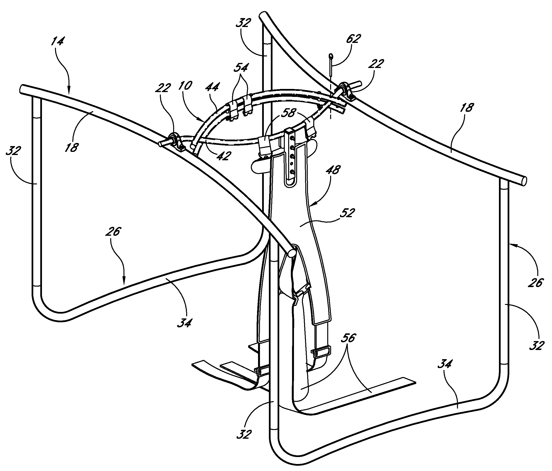
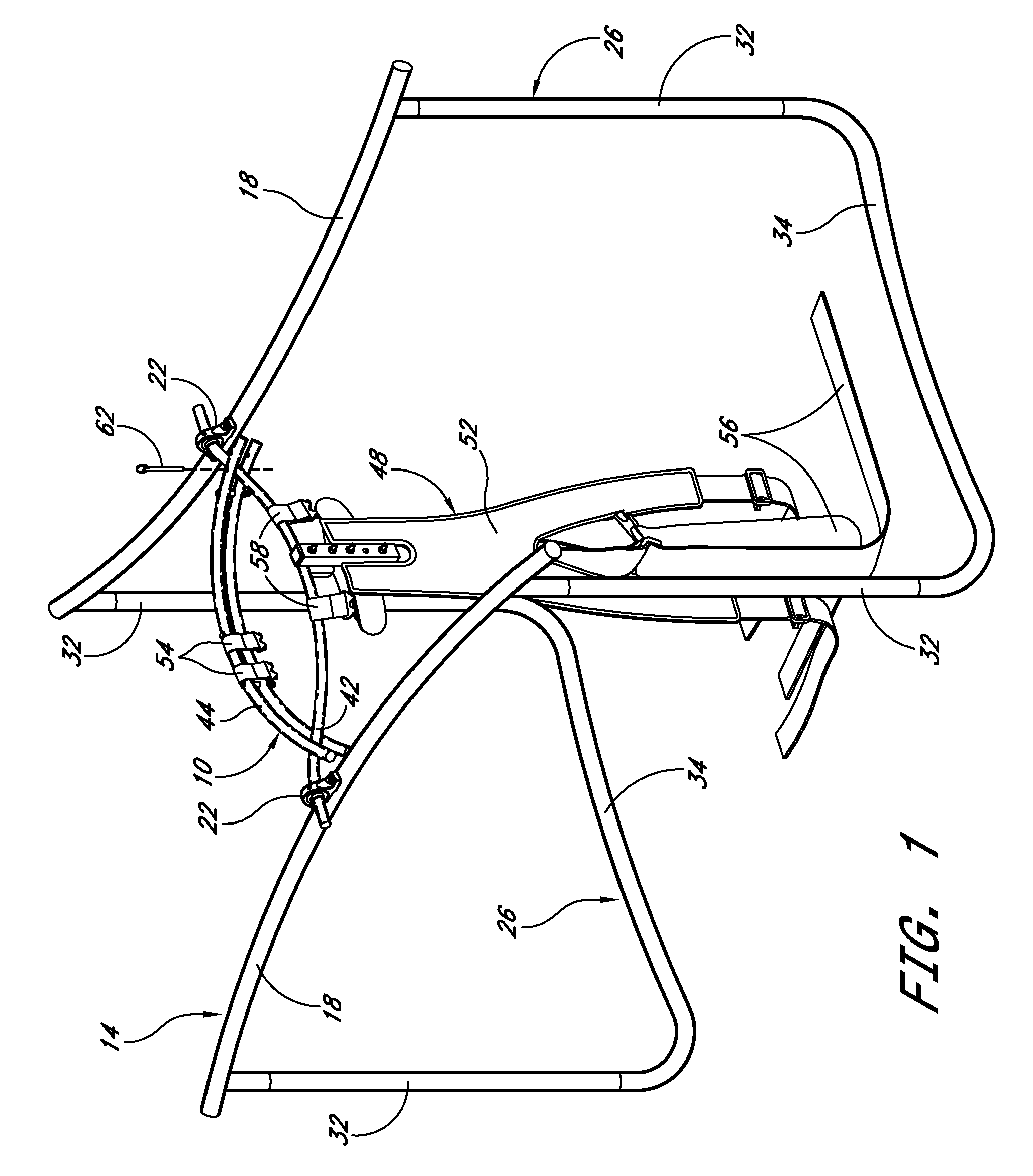
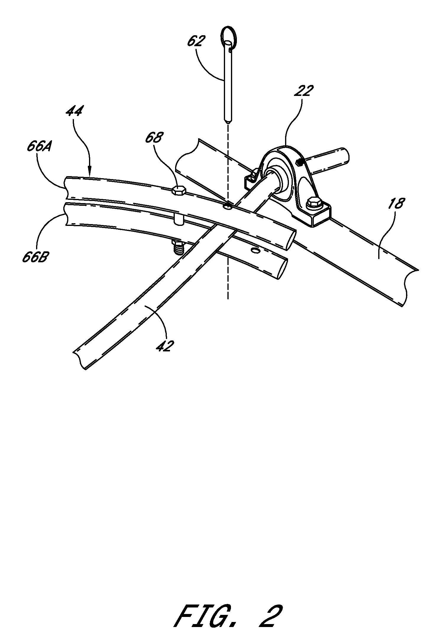
[0026]Reference is now made to the drawings wherein like numerals refer to like parts throughout. In FIG. 1, a spotting apparatus 10 is shown supported by a support frame 14. A pair of support brackets 18 receive the spotting apparatus 10, which is attached thereto using a pair of rotation brackets 22 to enable rotational movement of the spotting apparatus 10 relative to the pair of support brackets 18.

[0027]A pair of end supports 26 are located on each end of the pair of support brackets 18. U-shaped in form, each of the pair of end supports 26 consist of a pair of uprights 32 that are attached to one-another by a base connector 34. Each of the pair of uprights 32 is attached to a separate one of the pair of support brackets 18, with the resultant construction of the support frame 14 maintaining the latitudinal stability of the support brackets 18. A pair of telescopic adjustable bars 16 are attached towards the bottom of the U-shaped end support 26.

[0028]The spotting apparatus 10 ...


PUM


Abstract

An athletic trainer has a spotting apparatus received by a support frame. A pair of connected, spaced-apart lateral supports define the support frame and provide a pair of pivotal support surfaces that together provide a first axis of rotation, about which the spotting apparatus may selectively rotate. The spotting apparatus may consist of connected front and back braces with a ledge seat attached to the back brace for support and comfort. Alternatively, the spotting apparatus may be a unitary, substantially circular brace having an internal bearing raceway and attached support webbing that permit rotation about a second axis.

Description

CROSS-REFERENCE TO RELATED APPLICATION[0001]This application claims the benefit of U.S. Provisional Patent Application Ser. No. 60 / 804,265, filed Jun. 8, 2006.TECHNICAL FIELD[0002]The present invention relates generally to athletic training equipment and, more particularly, to such equipment for training athletes in gymnastics, acrobatics, and like athletic movements. More specifically, the present invention relates to a spotting apparatus utilizing a transportable frame to support a spotting seat cage in a manner providing a user with one or multiple axes of rotation within the support frame.BACKGROUND ART[0003]The worldwide popularity of Cirque du Soleil productions harkens back to the days of the big top and the “Greatest Show on Earth.” Acrobatic performers demonstrating advanced gymnastic procedures that communicate seemingly effortless artistry. Reality, of course, is quite different—the performers are highly skilled athletes that must continually train body and mind to accomp...

Claims


Application Information

Patent Timeline
Patent Type & Authority Applications(United States)
IPC IPC(8): A63B26/00A63B7/02
CPCA63B19/00A63B21/1419A63B19/04A63B2208/0285A63B2244/12A63B69/00A63B21/4009
Inventor CHARTRAND, PHILIPPE
Owner CHARTRAND PHILIPPE
Why Eureka
Try Eureka