Apparatus to maintain spinal alignment during the squat exercise

a technology of squat exercise and apparatus, which is applied in the direction of sport apparatus, gymnastic exercise, weights, etc., to achieve the effect of preventing lumbar spine flexion and distributing load on the trunk

Inactive Publication Date: 2007-12-13
MAC MILLAN MICHAEL
View PDF5 Cites 17 Cited by
  • Summary
  • Abstract
  • Description
  • Claims
  • Application Information

AI Technical Summary

Benefits of technology

[0008] The concept of the invention is to create from the single downward line of force application of the weight, two separate, opposing points of force application that pivot around a central axis. The source of the resistance is applied through this central pivot and along the mechanical axis of the spine and pelvis, just above the shoulders and behind the neck. The actual pivoting point does not contact the lifter, but instead, transmits the applied load to two opposing lever arms that extend out in opposite directions from this point. The front lever will consist of two parallel, padded rests which will go horizontally forward on either side of the head to reach the front of the shoulders. These lever arms, being positioned forward to the pivot, will tend to rotate upwards and backwards when force is applied to them from the front of the shoulders. The rear lever arm is also attached to the rotating pivot point, and extends posteriorly and vertically downward, towards the low back. When the lifter pushes upward onto the forward lever arms, the rear, lower arm (which is padded) rotates downwardly and forwardly to engage the small of the back. The net effect of the opposing rear and forward arms help protect the lifter in two ways. First, the rear arm applies pressure into the small of the back maintains the protective arched position. Second, the low back now shares the load of the applied force with the shoulders. Thus, the pivoting apparatus prevents flexion of the lumbar spine and distributes the load lower on the trunk.

Problems solved by technology

Second, the low back now shares the load of the applied force with the shoulders.

Method used


Image

  • Apparatus to maintain spinal alignment during the squat exercise
  • Apparatus to maintain spinal alignment during the squat exercise
  • Apparatus to maintain spinal alignment during the squat exercise

Examples


Embodiment Construction

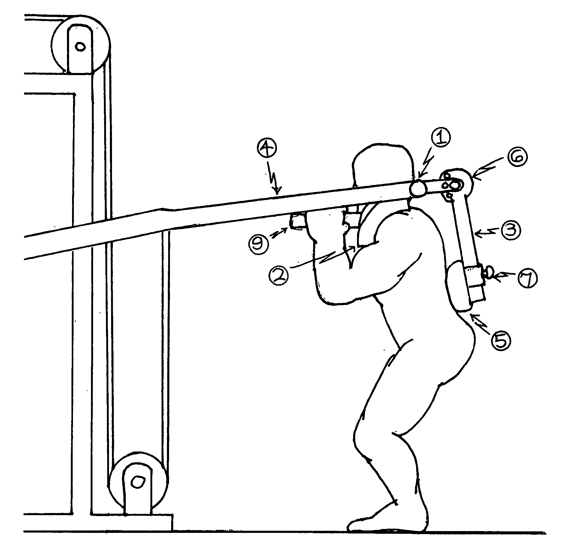
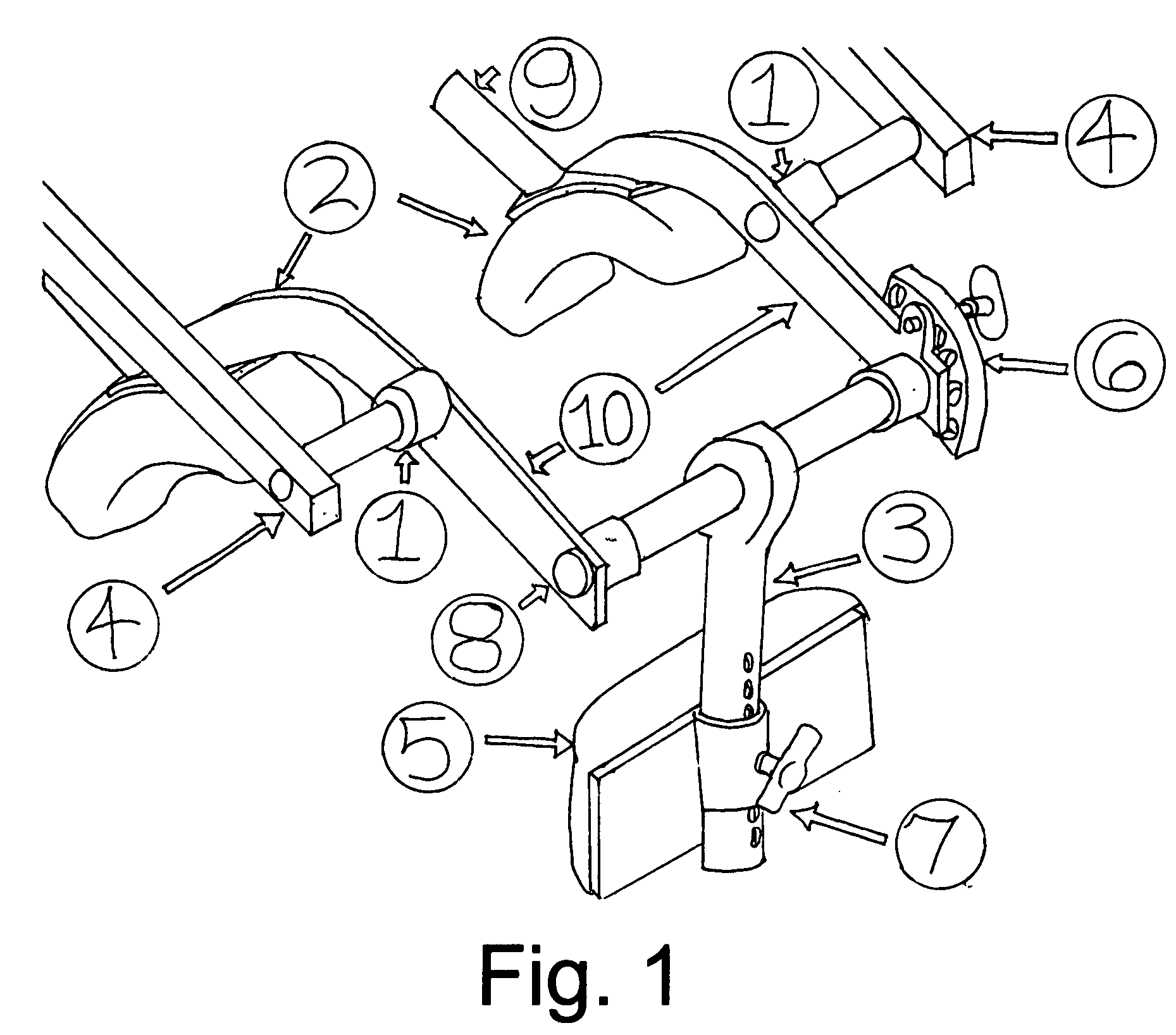
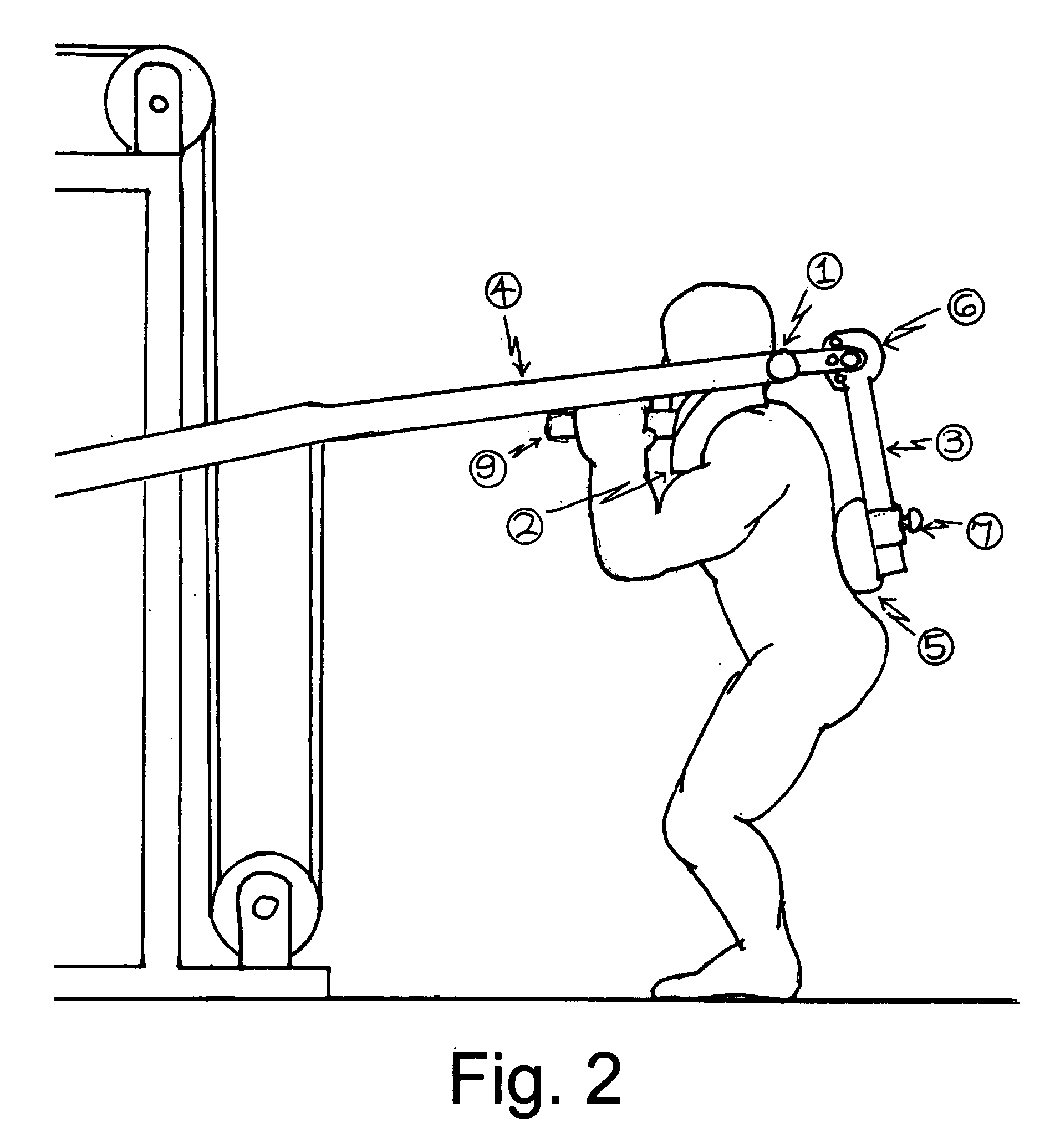
[0012] Referring to the drawings, wherein the reference numerals throughout both drawings refer to like parts on each drawing. The rotating central pivots, 1, are actually two like members, one on each side. As shown in FIG. 1, each rotating central pivot, 1, consists of first, a cylindrical sleeve attached on one end to a metal bracket, 10, with arms of the bracket extending out in both directions from the attachment point of the sleeve. The rotating central pivot, 1, is also comprised of a metal shaft or axle which is contained within the sleeve. As shown in FIG. 1, the shaft or axle which extends out of each rotating central pivot, 1, extends away from the sleeve and terminates onto and rigidly affixes to the resistance application lever, 4. In this preferred embodiment, the resistance for the performance of the squat exercise is delivered through the resistance application lever, 4, such that a weight or resistance that is applied in a downward direction to the resistance arm le...


PUM


Abstract

The invention is an apparatus that allows weight resistance to be applied to the upper torso during the performance of the squat exercise and actively aligns the spine to reduce the chance of spinal injury. The apparatus consists of a set of pads or rests on the shoulders in front of the spine which are connected through a pivot or lever to a lower back rest or pad behind the spine which create and maintain spinal alignment. The pivot between the front and back rests, is positioned over, but not contacting, the spinal axis of the user and is the point at which resistance is applied.

Description

CROSS REFERENCE TO RELATED APPLICATIONS [0001] I hereby claim the benefit of my earlier provisional patent application “Lumbar Load Sharing Upright Squat Apparatus”, application No. 60 / 809,216.BACKGROUND OF INVENTION [0002] Throughout history man has manipulated heavy loads by placing poles, yokes, and bars across the shoulders and behind the neck. In this position the load would lie directly along a vertical-axis that traveled almost exclusively through supporting skeletal structures. While resting behind the neck, a straight line can be drawn from the load through the body going directly towards the ground. This line of application lies along the mechanical axis of the spine passes through the center of the pelvis, and exits at the point where the heels are placed on the ground. By having the load transmitted through skeletal structures, this line of application can support large amounts of weight with little risk of injury. [0003] In industrialized societies, the use of shoulder-...

Claims


Application Information

Patent Timeline
Patent Type & Authority Applications(United States)
IPC IPC(8): A63B21/06A63B21/08
CPCA63B21/062A63B23/0233A63B23/0244A63B23/0405A63B21/1492A63B2208/0204A63B2208/0223A63B2230/62A63B2023/0411A63B21/0628A63B21/4047
Inventor MAC MILLAN, MICHAEL
Owner MAC MILLAN MICHAEL
Why Eureka
Try Eureka