Obstacle avoidance path computing apparatus, obstacle avoidance path computing method, and obstacle avoidance control system equipped with obstacle avoidance path computing system

a technology of obstacle avoidance and computing apparatus, applied in the direction of distance measurement, pedestrian/occupant safety arrangement, instruments, etc., can solve the problem that the avoidance control will not prevent the vehicle from reaching, and achieve the effect of improving the accuracy of the avoidance control

Inactive Publication Date: 2007-12-13
NISSAN MOTOR CO LTD
View PDF16 Cites 85 Cited by
  • Summary
  • Abstract
  • Description
  • Claims
  • Application Information

AI Technical Summary

Benefits of technology

[0007]The present invention was conceived in view of this issue in the above mentioned vehicle brake control system. One object of the present invention is to take velocity chan

Problems solved by technology

However, since there is a certain range within which the speed of the detected obstacle could change, there is the possibility that even if the system determ

Method used


Image

  • Obstacle avoidance path computing apparatus, obstacle avoidance path computing method, and obstacle avoidance control system equipped with obstacle avoidance path computing system
  • Obstacle avoidance path computing apparatus, obstacle avoidance path computing method, and obstacle avoidance control system equipped with obstacle avoidance path computing system
  • Obstacle avoidance path computing apparatus, obstacle avoidance path computing method, and obstacle avoidance control system equipped with obstacle avoidance path computing system

Examples


first embodiment

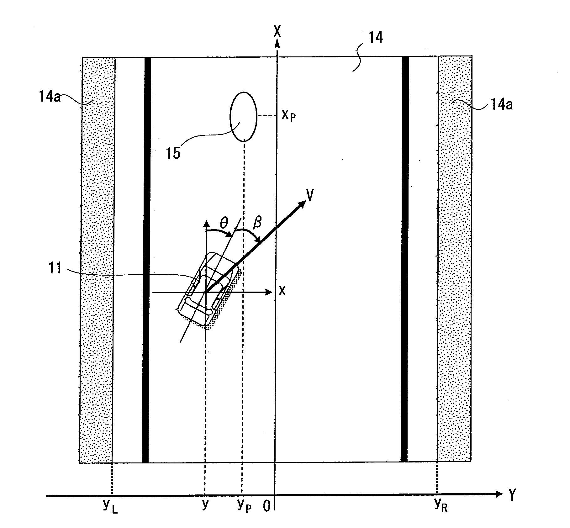
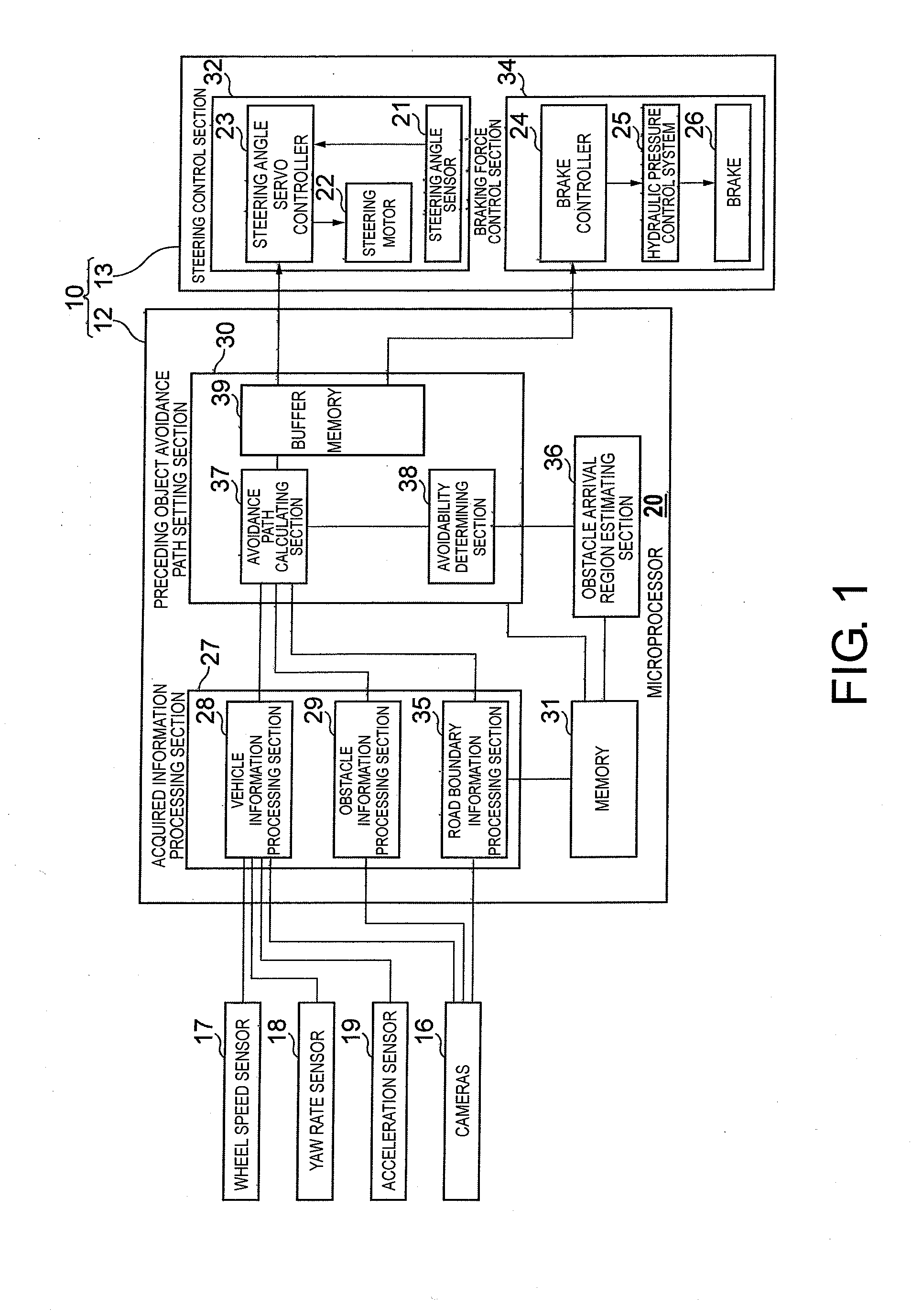
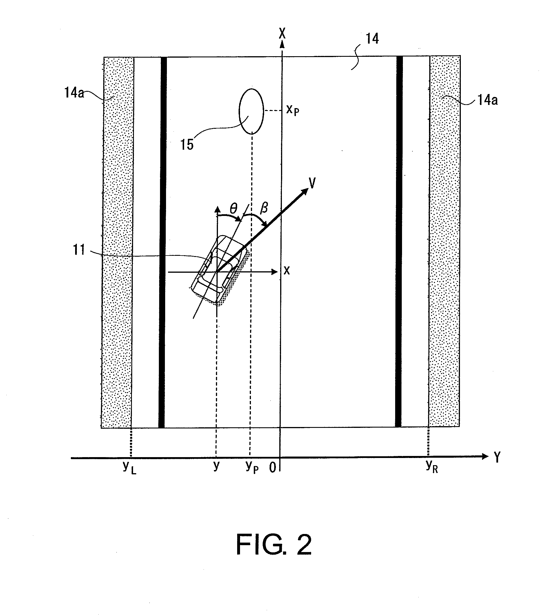
[0029]Referring initially to FIGS. 1 and 1, an obstacle avoidance control system 10 is illustrated in accordance with a first embodiment of the present invention. The obstacle avoidance control system 10 is installed in a vehicle 11 (hereinafter also called “the host vehicle”) as seen FIG. 2 when in use. The obstacle avoidance control system 10 includes an obstacle avoidance actuation amount calculating unit 12 and a vehicle motion control unit 13. The obstacle avoidance actuation amount calculating unit 12 is configured to calculate a driving operation actuation amount that will enable the host vehicle 11 to avoid an obstacle or object 15 when the obstacle or object 15 is detected on the road 14 on which the host vehicle 11 is traveling as seen FIG. 2. The vehicle motion control unit 13 is configured to execute the driving operation actuation amount calculated by the avoidance actuation amount calculating unit 12 so as to cause the host vehicle 11 to avoid the obstacle 15. As expla...

second embodiment

[0140]A second embodiment of an obstacle avoidance control system 100 in accordance with the present invention will now be explained with reference to FIGS. 14 to 17. The obstacle avoidance control system 100 of the second embodiment is basically the same as the obstacle avoidance control system 10 of the first embodiment, except that the avoidance control executed in order to avoided a detected obstacle 15 involves braking control only. Since the constituent features and operations of the obstacle avoidance control system 100 are the basically the same as those of the obstacle avoidance control system 10 of the first embodiment, detailed descriptions of the constituent features and operations that are the same are omitted for the sake of brevity.

[0141]FIG. 14 is a simple top plan view illustrating a vehicle 110 in which an obstacle avoidance control system 100 in accordance with the second embodiment is employed. FIG. 15 is a block diagram of the obstacle avoidance control system 1...


PUM


Abstract

An obstacle avoidance path computing apparatus is provided with a preceding object detecting section, a host vehicle information detecting section, a preceding object arrival region estimating section and a preceding object avoidance path setting section. The preceding object detecting section detects a preceding object. The host vehicle information detecting section detects host vehicle information. The preceding object arrival region estimating section calculates an estimated arrival region within which the preceding object could arrive after a prescribed amount of time has elapsed since the preceding object was detected, based on an estimated attribute of the preceding object from the preceding object information. The preceding object avoidance path setting section calculates an avoidance path that will not encroach on the estimated arrival region based the preceding object information and the host vehicle information.

Description

CROSS-REFERENCE TO RELATED APPLICATIONS[0001]This application claims priority to Japanese Patent Application No. 2006-163332 filed on Jun. 13, 2006. The entire disclosure of Japanese Patent Application No. 2006-163332 is hereby incorporated herein by reference.BACKGROUND OF THE INVENTION[0002]1. Field of the Invention[0003]The present invention generally relates to an obstacle avoidance control system and obstacle avoidance control method for enabling a vehicle to avoid an obstacle existing on a road on which the vehicle is traveling.[0004]2. Background Information[0005]Vehicle brake control systems have been proposed to determine the possibility of avoiding an obstacle existing in front of a host vehicle in which the system is employed and to control a host vehicle braking system applied to the host vehicle so as to avoid a collision. One example of such a vehicle brake control system is disclosed in Japanese Laid-Open Patent Publication No. 2004-155241. In this publication, it is ...

Claims


Application Information

Patent Timeline
IPC IPC(8): G05D1/00G01C22/00B60R21/00B60T7/12B60W10/18B60W10/188B60W10/20B60W30/00B60W30/09B60W30/095B60W40/105B62D5/04B62D6/00B62D101/00B62D111/00B62D113/00B62D137/00
CPCG05D1/0214G05D2201/0213G05D1/027G05D1/0246B62D15/0265B60W30/09B60W30/0956B60W30/10B60W2554/00B60W2554/80B60W2554/4029
Inventor NISHIRA, HIKARUDEGUCHI, YOSHITAKA
Owner NISSAN MOTOR CO LTD
Why Eureka
Try Eureka