
Anterior support device

a support device and anterior support technology, applied in the field of anterior support devices, can solve the problems of many individuals suffering from lower back pain and dysfunction, back pain and disability, etc., and achieve the effect of convenient manufacture and installation

Inactive Publication Date: 2007-12-20
PILGRIM INNOVATIONS
View PDF35 Cites 10 Cited by
  • Summary
  • Abstract
  • Description
  • Claims
  • Application Information

AI Technical Summary

Benefits of technology

[0012] Lastly, the anterior support device includes a knob secured to the second end of the threaded stem such that as the knob is rotated in a first direction, the threaded stem draws the angled surface of the first block against the angled surface of the first connecting member and draws the angled surface of the second block against the angled surface of the second connecting member. This, in turn, causes the first and second friction cups to lock tightly against the first and second ball joints, respectively, and maintains the padded rest in a desired orientation relative to the dental chair.
[0014] Another object of this invention is to provide an anterior support device which is easy to manufacture and install onto a dental chair.
[0015] Still another object of this invention is to provide an anterior support device that can be manipulated and locked in different positions in order to accommodate the various positions a dentist may assume adjacent to a patient who is seated in the dental chair.

Problems solved by technology

Many individuals suffer from lower back pain and dysfunction brought about by their work environment or other daily activities.
Repetitive or prolonged activities can be attributed as a major cause of this back pain and dysfunction.
This position contributes to posterior disc dysfunction and / or other factors which can lead to back pain and disability.
These devices, however, are designed to support the individual from the rear and thus are not effective for dentists and other individuals who must be in a forward bent position, or forward leaning position, as a fundamental part of their work, or other activity.

Method used


Image

  • Anterior support device
  • Anterior support device
  • Anterior support device

Examples


Embodiment Construction

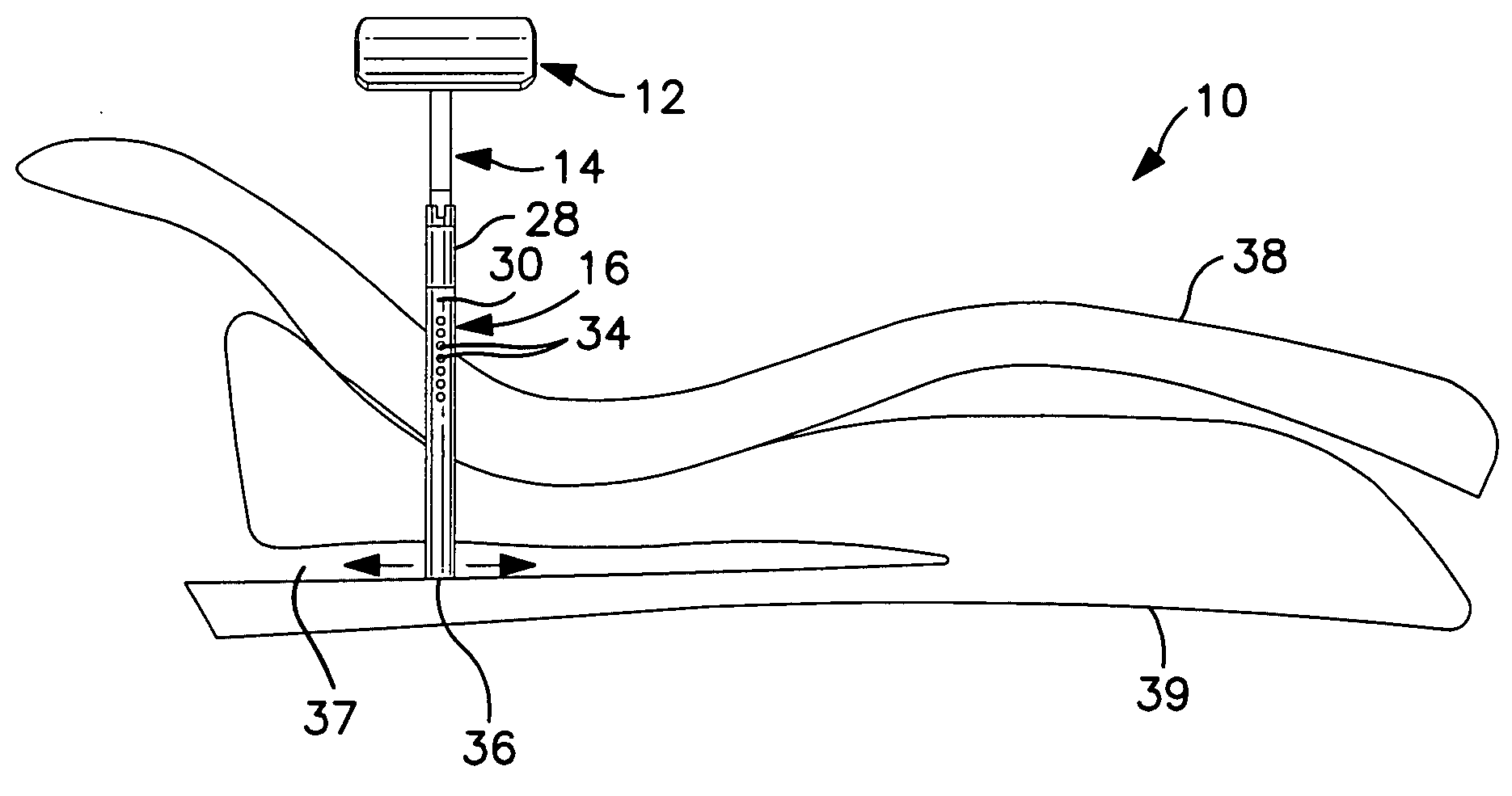
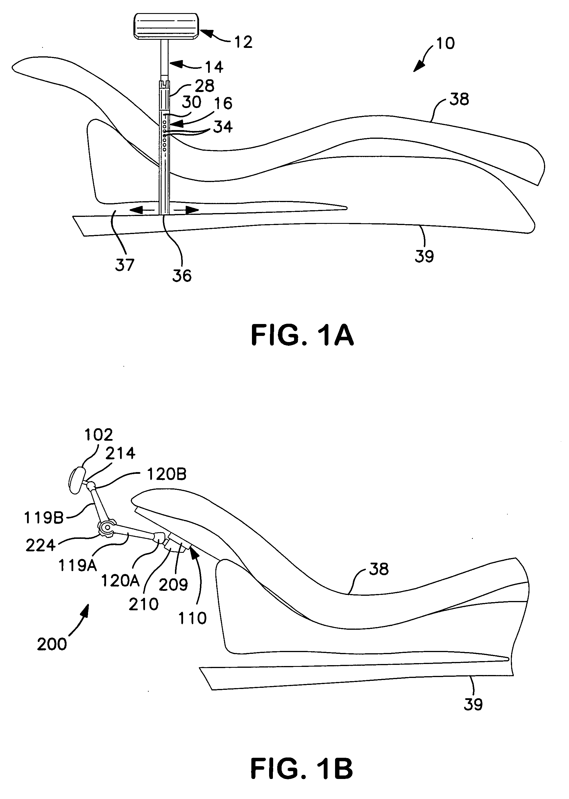
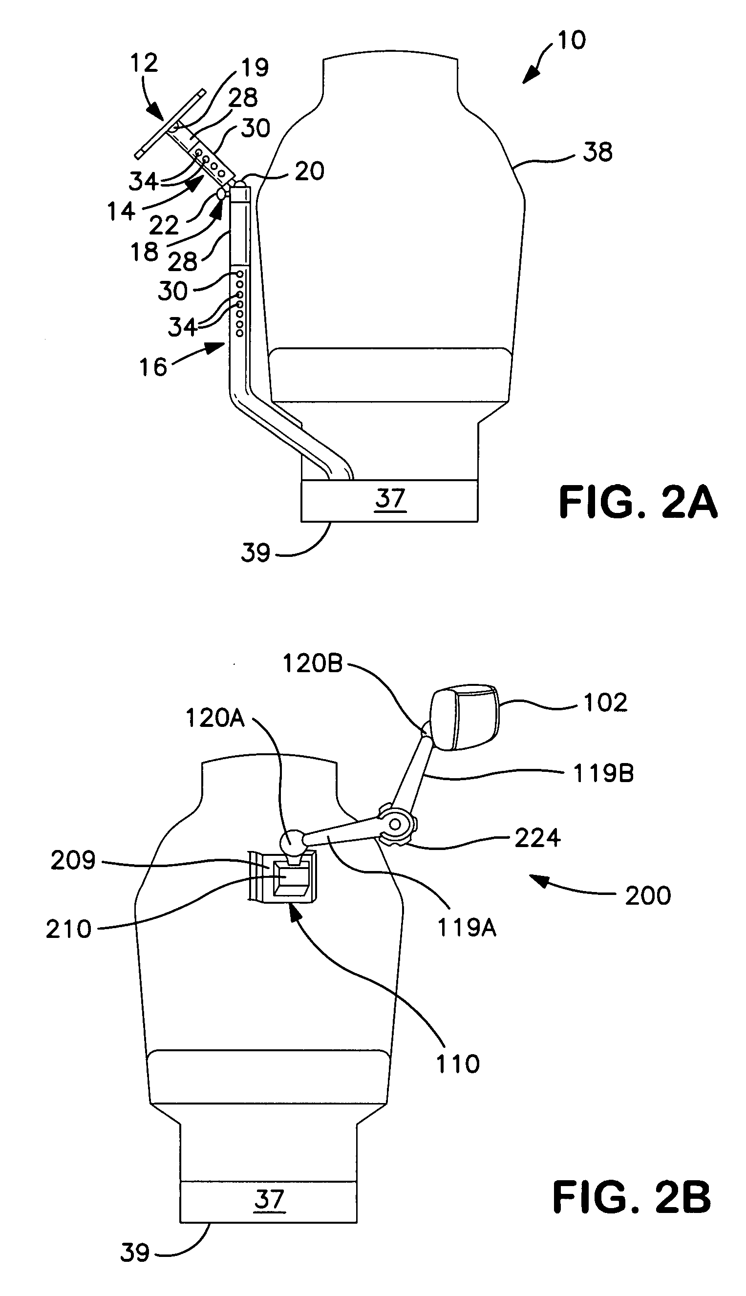
[0039] Referring to FIGS. 1A and 2A, an anterior support device 10 is shown which includes a padded rest 12, an angled bracket 14, and an upright bracket 16. The padded rest 12 can pivot with respect to the angled bracket 14. This pivoting is enabled due to the presence of a single or multi-axial pivot device 19, see FIG. 2A.

[0040] Still referring to FIG. 2A, the angled bracket 14 extends at an angle from the upright bracket 16 so that the padded rest 12 is positioned to support the practitioner near a patient seated in a dental chair 38. A coupler 18 is provided between the angled bracket 14 and the upright bracket 16 to allow the padded rest 12 to be tilted in any direction. Once the angular position of the angled bracket 14, with respect to the upright bracket 16, is adjusted to a desired position, the coupler 18 can be used to lock the angled bracket 14 in that desired position and angular orientation.

[0041] Referring now to FIG. 6, the coupler 18 is shown. The coupler 18 incl...


PUM


Abstract

An anterior support device for use with a dental chair is disclosed which can provide support for a user's torso while he is in a forward leaning position. The anterior support device includes an adapter directly or indirectly secured to the dental chair and a first pivotable connector secured to the adapter. A first movable rod engages the first pivotable connector. The support device further includes a padded rest against which a user can lean his or her torso and a second pivotable connector secured to the padded rest. A second movable rod engages the second pivotable connector and is also rotatably connected to the first movable rod. An actuating mechanism is connected to the first and second movable rods and enables the two rods to be locked in a set position to maintain the padded rest in a desired orientation relative to the dental chair.

Description

CROSS REFERENCE TO RELATED APPLICATIONS [0001] This application claims priority to Provisional Patent Application 60 / 867,157, filed Nov. 24, 2006, which is a Continuation-in-Part of patent application Ser. No. 10 / 833,652, filed Apr. 28, 2004, which is a Continuation-in-part of patent application Ser. No. 10 / 427,108, filed Apr. 30, 2003, which is a Continuation-in-Part of patent application Ser. No. 10 / 180,621, filed Jun. 26, 2002; all the above of which is incorporated herein by reference in its entireties. FIELD OF THE INVENTION [0002] This invention relates to an anterior support device for use in the health care industry and other environments where a person leans forward, leans forward repeatedly, and / or leans forward for extended periods of time. More specifically, this invention relates to an anterior support device for use with a dental chair. BACKGROUND OF THE INVENTION [0003] Many individuals suffer from lower back pain and dysfunction brought about by their work environmen...

Claims


Application Information

Patent Timeline
IPC IPC(8): A61G15/00
CPCA61G15/08A61B19/28A61B90/60A61C19/00A61G15/00A61G15/10
Inventor KLEMM, KURT W.BOOKS, GREGORY J.MACHEEL, GREG
Owner PILGRIM INNOVATIONS
Learn More