Relocatable countercurrent decantation system

a countercurrent decantation and countercurrent technology, applied in water/sewage multi-stage treatment, water treatment multi-stage treatment, separation process, etc., can solve the problems of high maintenance cost, high distance that the separated sand must travel to the sand disposal site, and high cost of transportation

Inactive Publication Date: 2007-12-20
CANADIAN OIL SANDS +6
View PDF5 Cites 30 Cited by
  • Summary
  • Abstract
  • Description
  • Claims
  • Application Information

AI Technical Summary

Benefits of technology

[0024]In one embodiment, the circuit is located at the mine site. The phrase “mine site” refers to an area of land presently undergoing open pit mining to excavate oil sand (mine pit) and which has one or more mine faces and one or more tailings retention facilities or tailings deposition ponds, which may be dike-enclosed areas or mined-out pits. In anothe

Problems solved by technology

Further, as the actively mined mine sites become more remote as the mine faces recede, the distance that the oil sand slurry must travel from the mine face to extraction and the distance that the separated sand must travel to sand disposal sites frequently exceeds

Method used


Image

  • Relocatable countercurrent decantation system
  • Relocatable countercurrent decantation system
  • Relocatable countercurrent decantation system

Examples


Embodiment Construction

[0042]The invention is exemplified by the following embodiments.

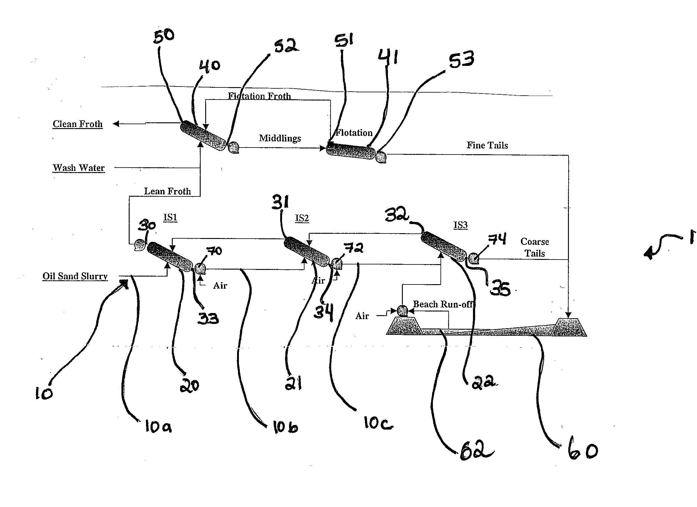
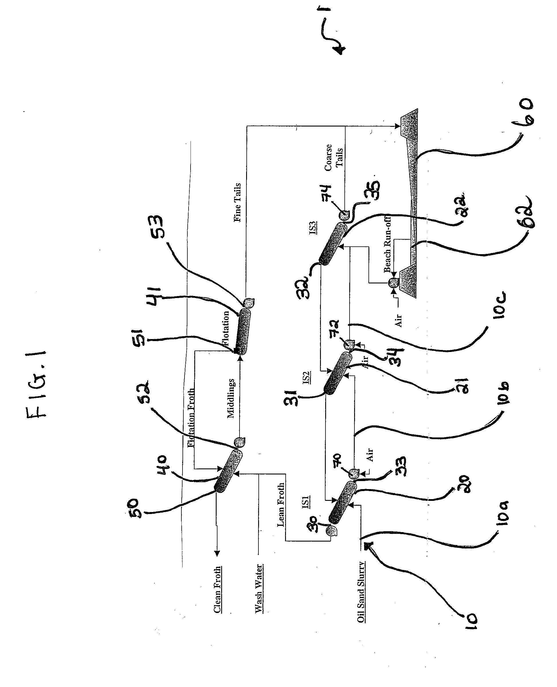
[0043]With reference first to FIG. 1, process line 1 comprises a series of countercurrently operating separators. More particularly, the separators used are inclined plate settlers 20, 21, 22, one of which is shown in more detail in FIG. 6. Process line 1 further comprises pipeline 10, which pipeline is divided into three pieces 10a, 10b and 10c. Pipeline 10b interconnects first inclined plate settler 20 to second inclined plate settler 21 and pipeline 10c interconnects second inclined plate settler 22 to third inclined plate settler 23.

[0044]Pipeline 10a feeds oil sand slurry to inclined plate settler 20, the first settler in the series. Overflow 30 is produced, which is referred to herein as the first product, which first product comprises bitumen, fines and water and is often referred to as lean froth. If desired, much of the fines and water in overflow 30 can be removed by delivering it to inclined plate settler 40 ...


PUM


Abstract

A process line for separating oil sand slurry comprising coarse solids, fines, bitumen and water, into a first product comprising bitumen, fines and water and a second product comprising coarse solids, fines and water is provided comprising a plurality of countercurrently operating solid/liquid separators arranged in series along a pipeline, wherein the underflow of one separator is fed to the next separator in series and the overflow of each separator is fed to the preceding separator, the underflow of the last separator being the second product and the overflow from the first separator being the first product.

Description

[0001]The present invention relates generally to a process and a circuit for producing a first product comprising bitumen, fines and water and a second product comprising coarse solids, fines and water, from oil sand. More particularly, the present invention relates to a process and a circuit comprising a countercurrent decantation assembly having a plurality of sand / liquid separators that may be mobile or relocatable.BACKGROUND OF THE INVENTION[0002]Oil sand, such as is mined in the Fort McMurray region of Alberta, generally comprises water-wet sand grains held together by a continuous matrix of viscous bitumen. It lends itself to liberation of the sand grains from the bitumen, preferably by slurrying the oil sand in hot process water, allowing the bitumen to move to the aqueous phase. Oil sand slurrying generally takes place in large, stationary slurry preparation or mixing towers. Once oil sand slurry is formed, the slurry is pumped through a pipeline at least 2.3 km long to the ...

Claims


Application Information

Patent Timeline
IPC IPC(8): C02F1/24
CPCB01D21/0006B01D21/0012B01D21/0045B01D21/245B01D21/26C02F2303/24B03D1/02C02F1/24C02F1/40C02F2101/32C02F2301/08B01D2221/04B01D21/0084
Inventor CYMERMAN, GEORGE J.VANDENBERGHE, JESSICA
Owner CANADIAN OIL SANDS
Why Eureka
Try Eureka