
Inductive charging of tools on surgical tray

a technology of inductive charging and surgical tray, which is applied in the field of inductive charging of electrical tools, can solve the problems of adding to the difficulty of maneuvering and performing surgery, and the difficulty of maintaining the sterility of power cords, so as to reduce the chance that a tool runs out of power, facilitate recharging, and maintain the sterility of tools.

Inactive Publication Date: 2007-12-20
BIOSENSE WEBSTER INC
View PDF11 Cites 68 Cited by
  • Summary
  • Abstract
  • Description
  • Claims
  • Application Information

AI Technical Summary

Benefits of technology

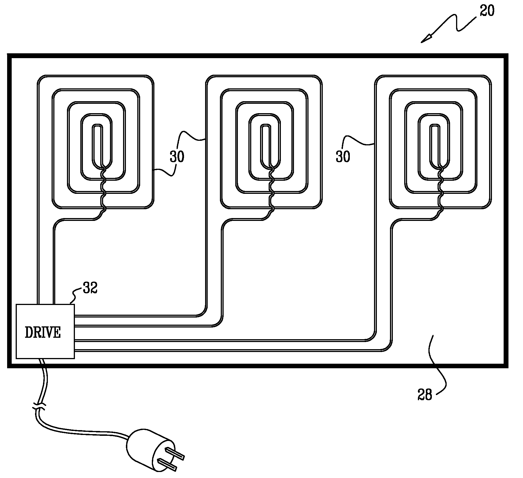
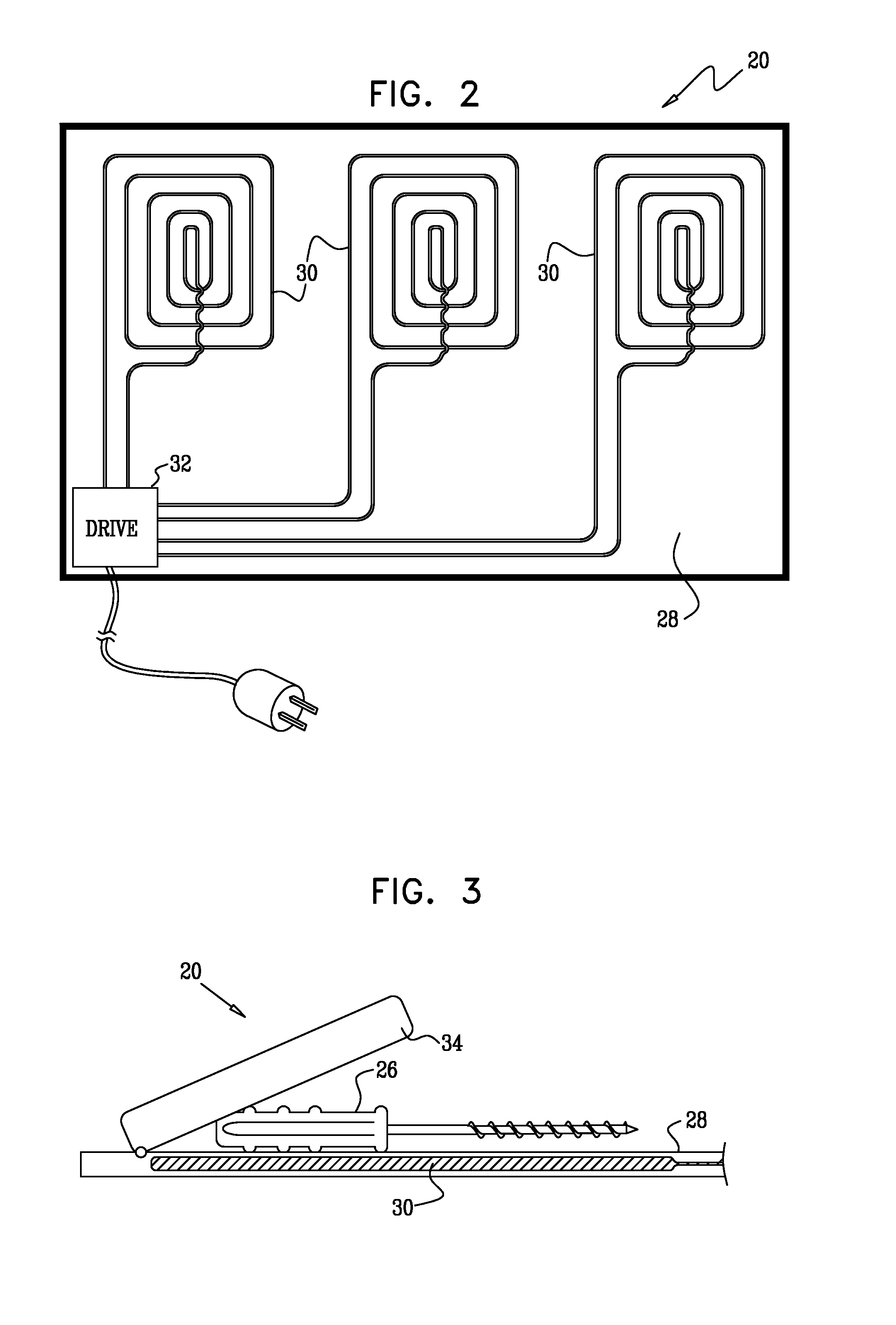
[0004]Embodiments of the present invention provide a charging tray for inductive charging of cordless electrical tools that simplifies recharging, while maintaining sterility of the tools. The tray may have the form of tool trays that are commonly used in the operating room. A magnetic field generator is located below the surface of the tray and generates a time-varying magnetic field of sufficient power at the surface of the tray so as to inductively charge tools that are placed on the tray. Inductive charging is advantageous in this context since it does not require that there be any physical contact between the field generator and the tools. The tools are recharged whenever they are placed on the tray, thus reducing the chances that a tool will run out of power in the course of a procedure.

Problems solved by technology

Operating rooms are often crowded with personnel and equipment, and electrical cords for powered surgical tools add to the difficulty of maneuvering and performing the operation.
Maintaining the sterility of power cords can also be problematic.

Method used


Image

  • Inductive charging of tools on surgical tray
  • Inductive charging of tools on surgical tray
  • Inductive charging of tools on surgical tray

Examples


Embodiment Construction

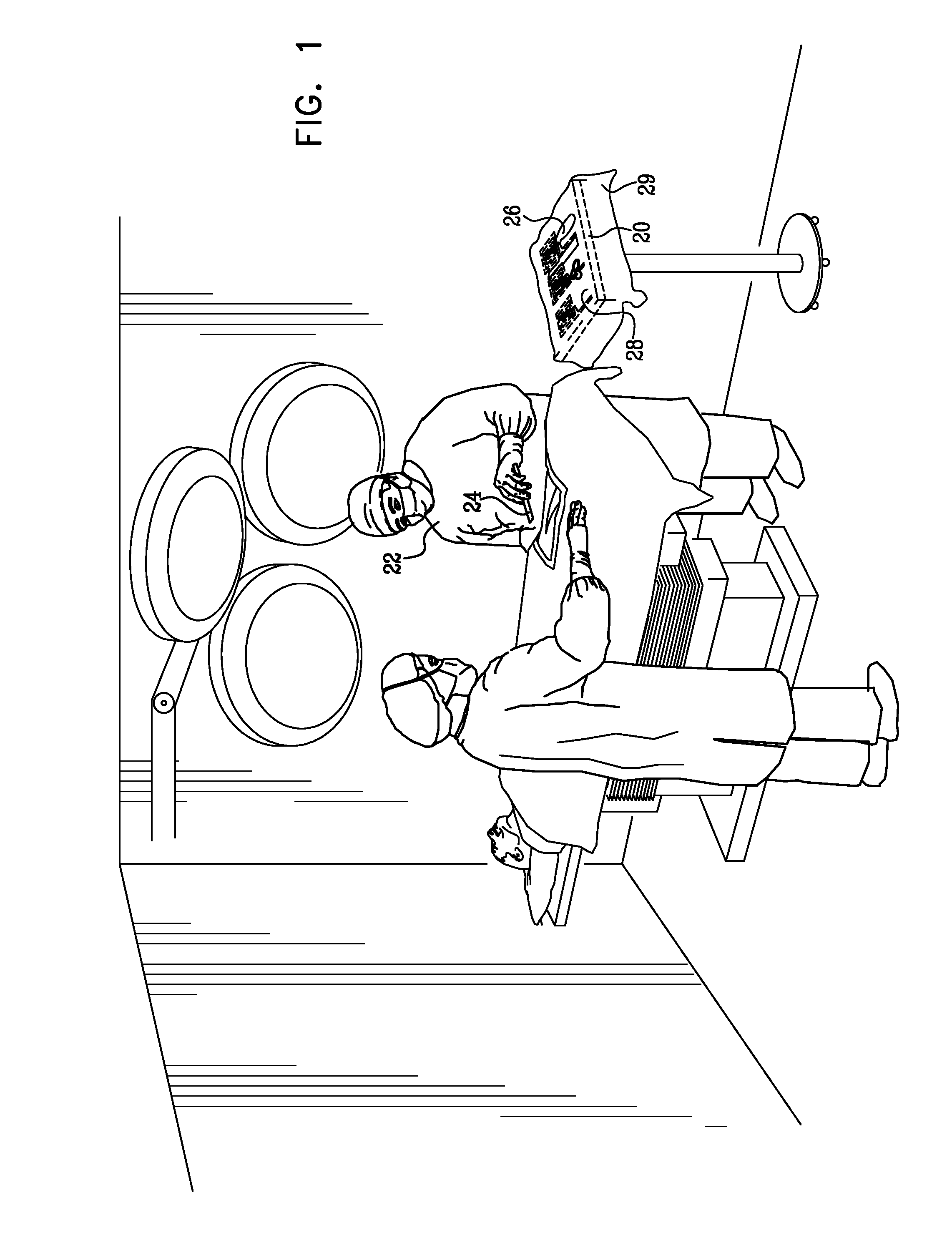
[0025]FIG. 1 is a schematic, pictorial illustration showing a tool tray 20 with inductive charging capability in use during a surgical procedure, in accordance with an embodiment of the present invention. A surgeon 22 uses cordless, electrically-powered tools 24, 26 during the procedure. When a given tool is not in use, the surgeon places it on a surface 28 of tool tray 20. While the tool is on the tray, it is inductively charged by a magnetic field produced by a field generator below the surface of the tray (shown in the figures that follow).

[0026]Tool tray 20 and tools 24, 26 may be designed, as described hereinbelow, so that the tools are charged regardless of the orientation in which they are placed on the tray. The charging magnetic field may be concentrated in one area of the tray, or it may be generated over the entire tray surface, so that the tool is charged regardless of location on the tray, as well. Thus, there is no need for receptacles to hold the tools on the tray. Su...


PUM


Abstract

Electrical apparatus includes a tray, having a surface on which a tool containing a rechargeable power source can be placed, and a magnetic field generator, which is located below the surface of the tray and is operative to generate a time-varying magnetic field of sufficient power at the surface of the tray so as to inductively charge the power source in the tool.

Description

FIELD OF THE INVENTION[0001]The present invention relates generally to cordless electrical tools, and specifically to methods and devices for inductive recharging of electrical tools used in medical procedures.BACKGROUND OF THE INVENTION[0002]Electrical surgical tools are commonly used in operating rooms. For example, electrocautery devices are used in many procedures, and orthopedists commonly use power saws and drills. Operating rooms are often crowded with personnel and equipment, and electrical cords for powered surgical tools add to the difficulty of maneuvering and performing the operation. Maintaining the sterility of power cords can also be problematic. In response to these difficulties, cordless, battery-powered surgical tools, such as cordless orthopedic drills and saws, are becoming increasingly popular.[0003]In the course of a surgical procedure, the battery in a surgical tool may run down. In this case, the battery must be recharged or replaced while maintaining sterile...

Claims


Application Information

Patent Timeline
Patent Type & Authority Applications(United States)
IPC IPC(8): H02J7/04A61B46/23
CPCA61B19/0271H02J7/025H02J7/0042A61B2017/00734A61B50/33H02J50/402H02J7/0044H02J50/10H02J2310/23A61B18/10A61B18/00A61B18/08H02J50/12
Inventor GOVARI, ASSAFALTMANN, ANDRES CLAUDIOEPHRATH, YARON
Owner BIOSENSE WEBSTER INC
Learn More