
Systems and methods of capturing high-resolution images of objects

Inactive Publication Date: 2007-12-20
WAVETRONEX
View PDF26 Cites 84 Cited by
  • Summary
  • Abstract
  • Description
  • Claims
  • Application Information

AI Technical Summary

Benefits of technology

[0029]In view of the foregoing and other problems of the conventional methods, it is, therefore, an object of the present invention to provide a method and

Problems solved by technology

However, many applications that require security cameras do not have the luxury of dedicated 24-hour security camera operators every day, and the more basic models of observation and data recording must suffice.
Yet, a common complaint from most users of those systems is that although they have images of the action, or perpetrator, the lower-resolution image quality obtained from the wide-angle cameras typically used to survey wide areas prevents clear identification.
Digital zoom enhancement cannot recover this original loss of resolution.
In order to rectify this problem, camera and sensor manufacturers provide consumers with higher resolution cameras, which can improve the resolution but often come with higher prices or higher storage requirements and still may be far from the resolution ultimately required for adequate object identification.
These systems do not address the timing and security issues related to the clarification of identity or source.
Secondly, it applies more to bandwidth (i.e., size) reduction than higher resolution image recording.
Thirdly, it is not directed at security applications.
Fifthly, it fails to describe any apparatus.
Sixthly, it fails to describe actual techniques.
Seventhly, it is limited to face-detection, not all objects.
Firstly, they do not apply directly to faces or other objects.
Secondly, audio signals are required to apply the claimed techniques.
Secondly, its system needs two cameras.
Firstly, it does not use automated object detection techniques.
Secondly, its techniques are not well defined and would be very hard to realize.
Firstly, it applies audio data instead of visual data.
Secondly, it applies an audio sensor array to calculate a position for directing hardware instead of using object detection.
Firstly, it applies to audio data instead of visual data.
Secondly, it applies an audio sensor array to calculate a position for directing hardware instead of object detection.
Its disadvantage is that it requires audio, not visual data.
Firstly, masks have to be applied to more than the start or “home” position.
Secondly, masks have to be defined manually.
Its disadvantage is that it concerns with the transfer of tracked objects to other cameras.
Firstly, it does not adequately describe the “adaptive” pattern recognition algorithm employed.
Secondly, its predictive system would probably not work as described without a more substantial definition of its pattern recognition technology.
Secondly, it fails to disclose any hardware application.
Its disadvantage is that it is concerned with finding the region of the image by “defining a region of interest” using an audio signal.
Firstly, it is fundamentally for tracking instead of for obtaining and recording high-resolution images.
Secondly, it applies to robots and teleconferencing.
Thirdly, it has no direct relationship to generalized object detection or tracking.
Firstly, it relates to audio signals instead of video signals.
Secondly, it fails to describe the hardware.
Firstly, they relate to audio signals instead of video signals.
Secondly, their camera image is related to a direction, not a specific object.
Thirdly, they are not related to object detection.
Firstly, its motion detection technique is highly specialized for particular equipment.
Secondly, its system operates with step cameras that require calibration.
Its disadvantage is that its system requires the physical modification of the objects tracked.
Its disadvantage is that its object detection method requires specialized equipment and double exposures.
It has the disadvantage that the system requires the object of interest to be selected by the user, which is not the same as if the object is automatically detected by the system.

Method used


Image

  • Systems and methods of capturing high-resolution images of objects
  • Systems and methods of capturing high-resolution images of objects
  • Systems and methods of capturing high-resolution images of objects

Examples


Embodiment Construction

[0038]The present invention is described in more detail by referring to the accompanying drawings. The drawings are to describe the preferred embodiments. However, the present invention is exemplified with several embodiments but is not limited by said embodiments. Said embodiments are to disclose the scope of protection of the present invention to persons of ordinary skill in the art in more detail.

Basic Description of Track-Zoom Function

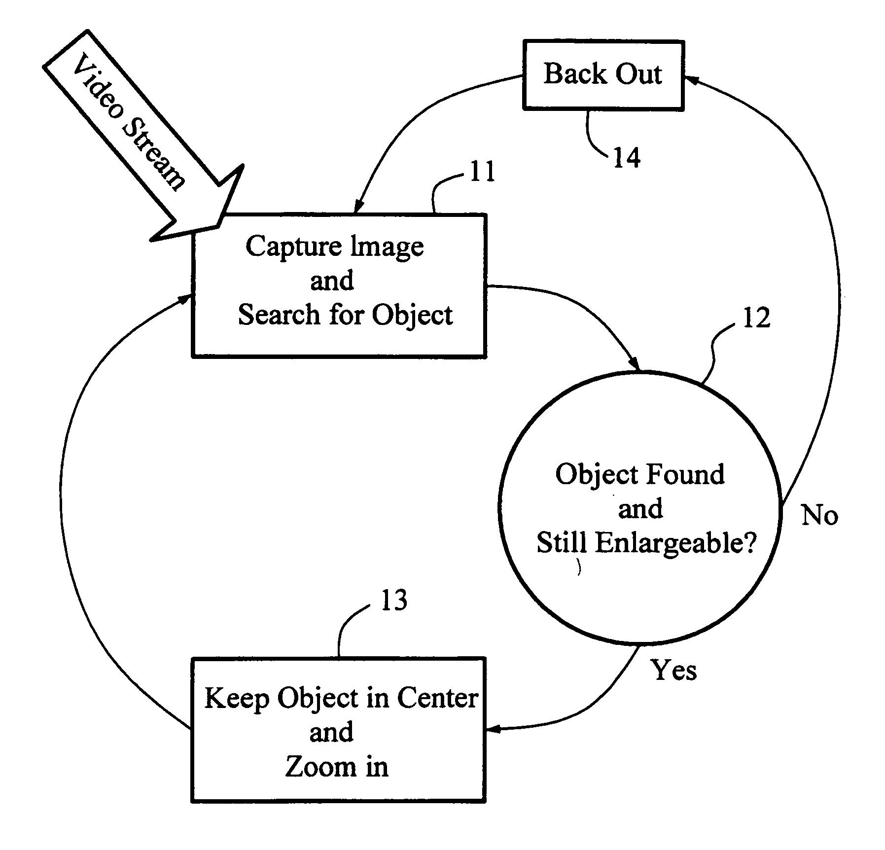
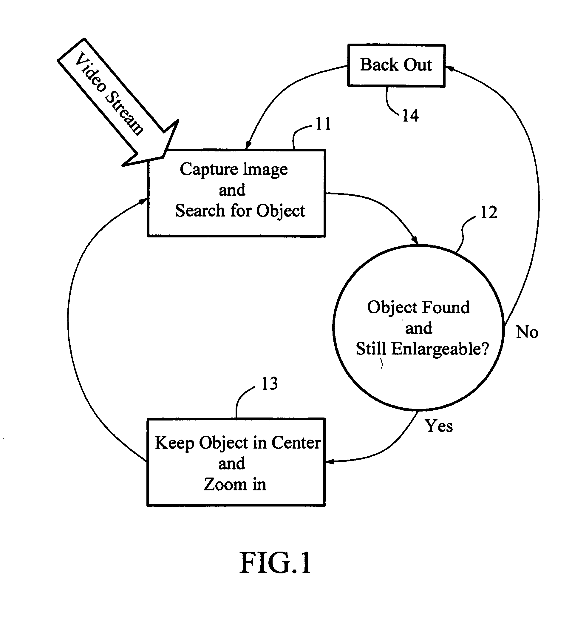
[0039]The track-zoom function is fundamentally the reaction of a directional zoom camera to the detection of an object in a video window. The camera direction and amount of zoom are varied in order to move the object into the center of the image at the largest possible size in relation to the entire video window, or best resolution.

[0040]FIG. 1 shows a simple flow chart of the track-zoom function. The process captures images in a video stream with a pan, tilt, zoom (PTZ) camera, or a zoom camera mounted on a pan / tilt platform, and applies an object...


PUM


Abstract

The invention relates to a system of capturing zoom-in images of an object. The system comprises a pan, tilt, zoom (PTZ) camera for capturing a video stream in view; an image-capture device for extracting and digitizing images from the video stream; an object detector for detecting objects in the images from the image-capture device, determining the locations and sizes of the objects and sending the locations and the sizes of the objects to a selector; the selector for determining one of the objects and sending the location and size of the one of the objects to a assessor; the assessor for determining the trajectories required to both align the one of the objects to the center of the image based on the current location of the one of the objects relative to the center and to maximize the size and resolution of the one of the objects according to the current size of the one of the objects, and for sending the trajectories to a translator; the translator for converting the trajectories into a signal stream with a command format that a camera controller can understand and for sending the converted trajectories to the camera controller; and the camera controller for moving and zooming the PTZ camera according to the signal stream, thereby the PTZ camera moves to center on the one of the objects and captures zoomed-in images of the one of the objects from the video stream.

Description

FIELD OF THE INVENTION[0001]The present invention relates to video security and, more particularly, to the use of object detection technology combined with automated directional optical zoom cameras to track, obtain, and record high-resolution zoomed-in images of objects such as faces or human figures and the times at which they were captured.BACKGROUND OF THE INVENTION[0002]Most automated digital video camera-based security applications that exist today are fixed cameras operating over a broad viewing area. They simply record video streams of the entire scene so that if something happens, there is a record of the activity. More advanced systems have moving cameras that scan a wider area by automatically panning the fixed camera over an extended viewing range using various forms of platforms and motors.[0003]Using pan, tilt and zoom cameras, human operators can survey an area in more detail, and are able to direct cameras in order to capture and record close-up, high-resolution imag...

Claims


Application Information

Patent Timeline
IPC IPC(8): H04N7/14
CPCG01S3/7865G06T7/208H04N5/77H04N5/232H04N5/23296G08B13/19608G06T7/277H04N23/69
Inventor PETERSEN, BARRY LEECHAN, LI SHENHUANG, HUI PINGCHU, CHIA CHINGLEE, HOU HSIENWANG, TSAI TELI, CHANG JOU
Owner WAVETRONEX
Features
  • Generate Ideas
  • Intellectual Property
  • Life Sciences
  • Materials
  • Tech Scout
  • Unparalleled Data Quality
  • Higher Quality Content
  • 60% Fewer Hallucinations
Learn More