Abnormality judging apparatus

Inactive Publication Date: 2007-12-20
JTEKT CORP
View PDF8 Cites 12 Cited by
  • Summary
  • Abstract
  • Description
  • Claims
  • Application Information

AI Technical Summary

Benefits of technology

[0013]It is another object to provide an abnormality judging apparatus capable of adjusting a threshold value so as to also reliably detect an abnormality that variations in the output of the resolver are minor, by accepting a predetermined range for the difference between a threshold value and a value calculated based on a value received from a resolver for use in judging whether or not abnormality has occurred.

Problems solved by technology

When the rotation angle signal cannot be outputted due to the occurrence of some abnormality such as shorting at the coil or the rotor in the resolver, the control and so on of the brushless motor cannot be normally exercised.
However, in the apparatus described in Japanese Patent Application Laid-Open No. 2002-104212, there are individual differences among the resolvers, and therefore output signals vary.
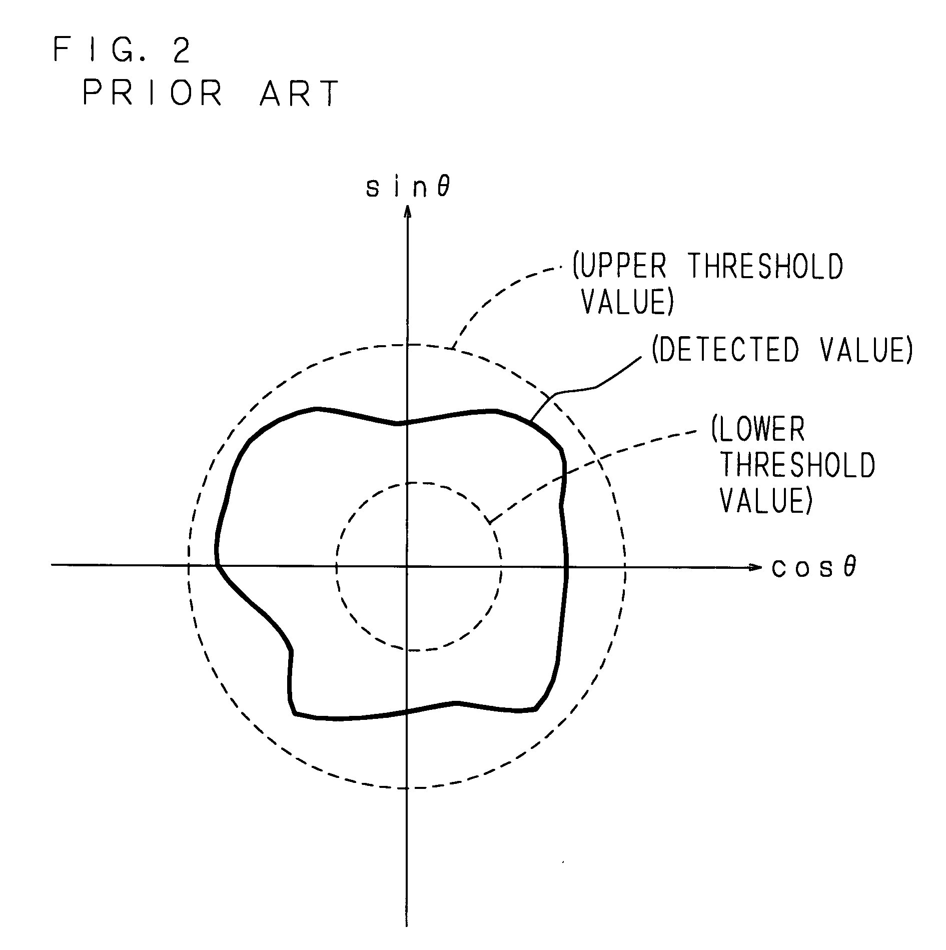
Because of this, there have been problems that there is a need to broadly set a range of between the upper threshold value and lower threshold value in general as shown in FIG. 2 and it is impossible to reliably detect even abnormalities such as shorting at the layers of a coil that variations in output are minor.
Moreover, although it can also be considered that no individual differences are made by making high-precision resolvers in order to solve the above problems, there has been a problem that the production cost of the resolvers rise considerably.

Method used


Image

  • Abnormality judging apparatus
  • Abnormality judging apparatus
  • Abnormality judging apparatus

Examples


Embodiment Construction

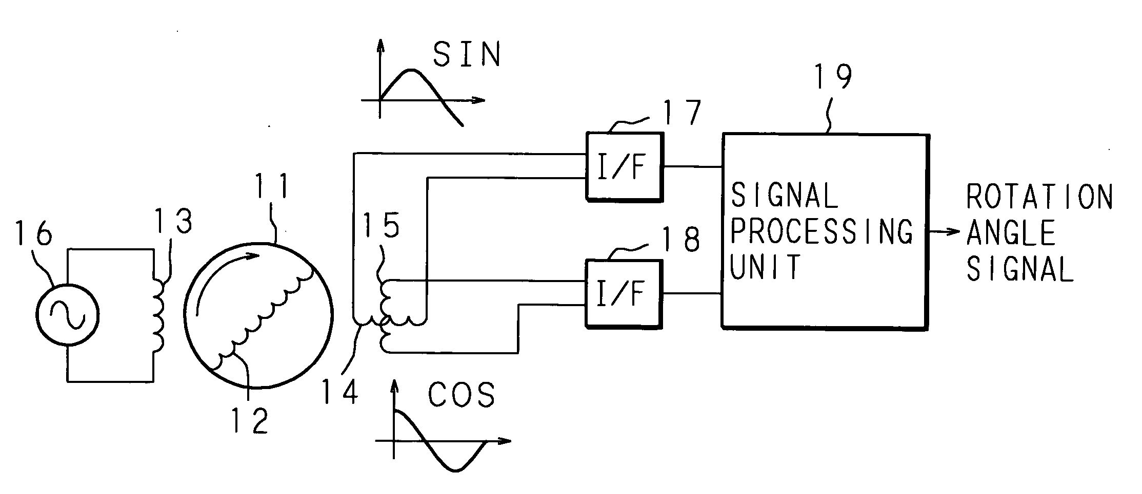
[0027]The present embodiment will now be described below with reference to the drawings. FIG. 3 is a block diagram of the configuration of an abnormality judging apparatus. In FIG. 3, reference numerals 21 and 22 denote interfaces (receiving units) which receive a sine wave signal sent from an interface 37 of a resolver and a cosine wave signal sent from an interface 38 of the resolver. The abnormality judging apparatus comprises a signal arithmetic circuit (calculating unit) 23 which calculates successively the sum of each square of the sine wave signal and cosine wave signal received from the interfaces 21 and 22 respectively, a memory (storing unit) 24 which stores the value of the sum of each square calculated by the signal arithmetic circuit 23 at a predetermined point in time as a threshold value, a judging circuit (judging unit) 25 which judges whether or not the difference between the value calculated successively by the signal arithmetic circuit 23 and the value stored in t...


PUM


Abstract

An abnormality judging apparatus of a rotation angle detecting apparatus generating a sine wave signal and a cosine wave signal according to the rotation angle of a rotor is provided with an interface which receives the sine wave signal, an interface which receives the cosine wave signal, a signal arithmetic circuit which successively calculates the sum of each square of the received sine wave signal and cosine wave signal, a memory which stores as a threshold value the value of the sum of each square of the sine wave signal and cosine wave signal received from the rotation angle detecting apparatus at a predetermined point in time, and a judging circuit which judges that abnormality has occurred at the rotation angle detecting apparatus when the difference between the value calculated by the signal arithmetic circuit and the value stored in the memory is out of a predetermined range.

Description

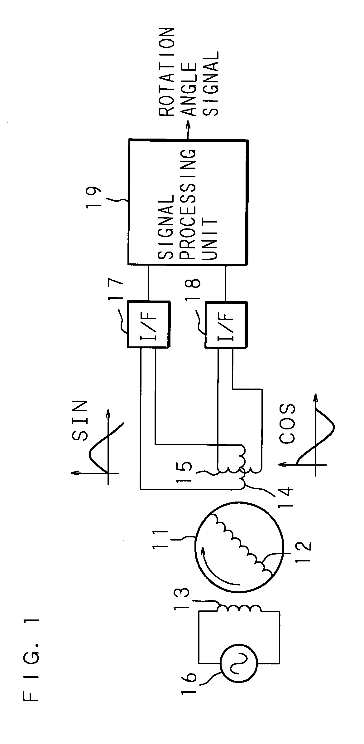
CROSS-REFERENCE TO RELATED APPLICATIONS[0001]This Nonprovisional application claims priority under 35 U.S.C. §119(a) on Patent Application No. 2006-151250 filed in Japan on May 31, 2006, the entire contents of which are hereby incorporated by reference.BACKGROUND[0002]1. Technical Field[0003]The present invention relates to an abnormality judging apparatus which judges whether or not abnormality has occurred at a rotation angle detecting apparatus based on a sine wave signal and a cosine wave signal generated according to the rotation angle of a rotor detected by the rotation angle detecting apparatus.[0004]2. Description of Related Art[0005]In conventional electric power steering (EPS) systems with brushless motors, the rotation angle of the brushless motor is detected by using a resolver, and then the amount of electric current through the brushless motor is controlled based on the detected rotation angle. FIG. 1 is a block diagram of the configuration of a resolver and FIG. 2 is ...

Claims


Application Information

Patent Timeline
IPC IPC(8): H02H7/08B62D5/04G01D5/12G01D5/244
CPCG01D5/24461G01D5/2073G01D3/08
Inventor NISHIMOTO, MITSUHIKOSUGIMOTO, EIKI
Owner JTEKT CORP
Why Eureka
Try Eureka