Apparatus and method for detecting signal in multi-input multi-output system

a multi-input, multi-output technology, applied in diversity/multi-antenna systems, polarisation/directional diversity, amplitude demodulation, etc., can solve the problem of increasing computation complexity, increasing computation amount and computation complexity, and more memory space, etc. problem, to achieve the effect of low computation complexity and high performan

Inactive Publication Date: 2007-12-20
SAMSUNG ELECTRONICS CO LTD +1
View PDF0 Cites 31 Cited by
  • Summary
  • Abstract
  • Description
  • Claims
  • Application Information

AI Technical Summary

Benefits of technology

[0013]Another aspect of the present invention is to provide an apparatus and method for detecting a signal with a low computation complexity and a high performance using a modified stack algorithm in a MIMO system

Problems solved by technology

However, since a computation amount and a computation complexity exponentially increase in the Viterbi decoding scheme, it has been difficult to use the Viterbi decoding scheme when a constraint length is 10 or more.
However, there is a demerit in that more memory space is required.
In order to avoid the memory overflow, a scheme has been proposed in which memory reallocation is achieved so that a memory space is maintained to M. However, in this scheme, performance is inferior to a Maximum Likelihood (ML) scheme.
Although performance can be improved by reducing the memory space, this is not a proper solution because errors may frequently occur during a decoding process when the memory space is reduced.
In particular, the ZF scheme and the MMSE scheme, each of which is included in the linear scheme, have a limit in supporting a plurality of users.
This is because performance deterioration becomes significant as the number of users increases.
However, in spite of its excellent performance, the ML scheme has a problem in requiring a high computation complexity.

Method used


Image

  • Apparatus and method for detecting signal in multi-input multi-output system
  • Apparatus and method for detecting signal in multi-input multi-output system
  • Apparatus and method for detecting signal in multi-input multi-output system

Examples


Embodiment Construction

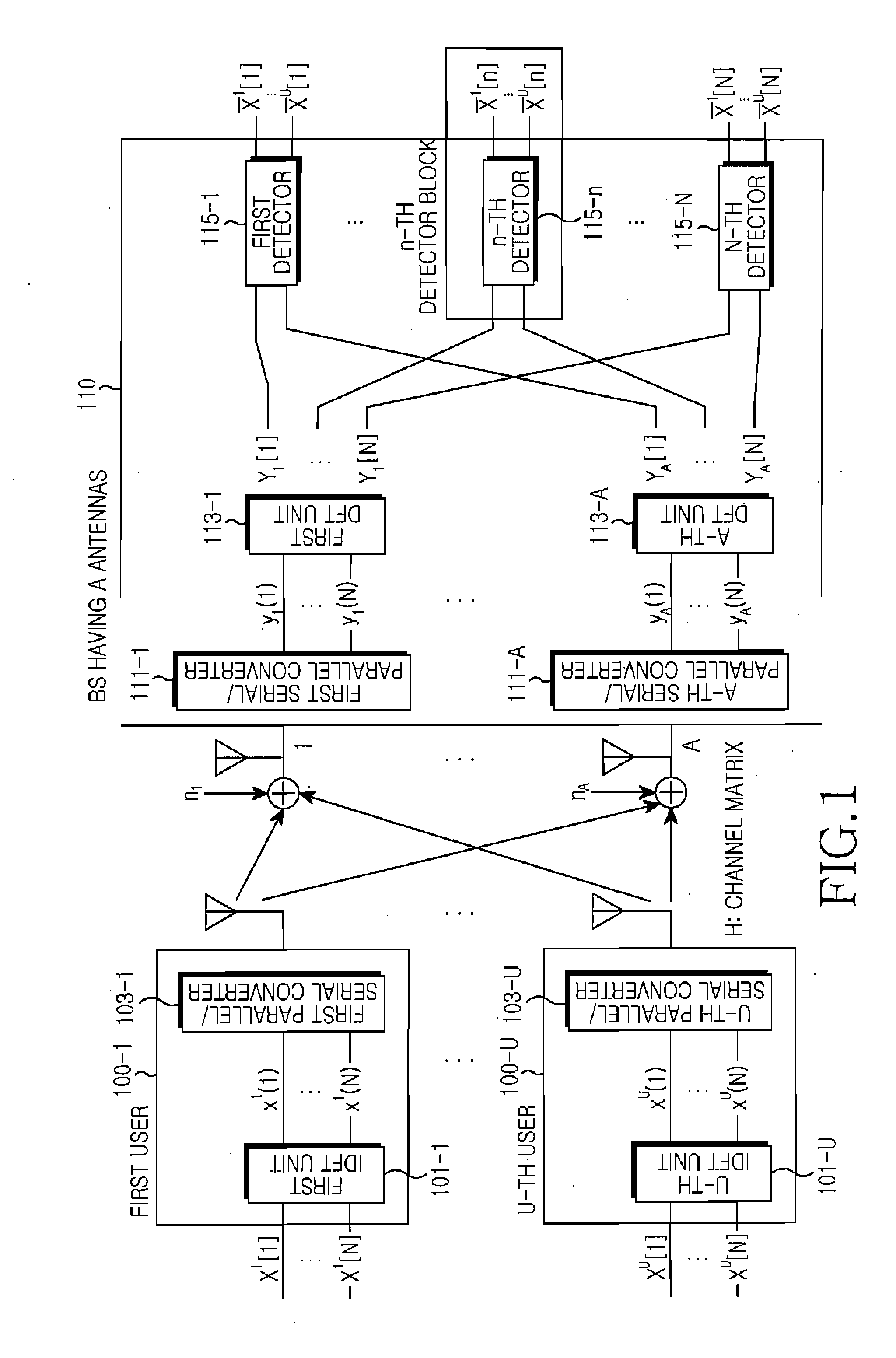
[0026]The following description with reference to the accompanying drawings is provided to assist in a comprehensive understanding of the exemplary embodiments of the present invention as defined by the claims and their equivalents. It includes various specific details to assist in that understanding but these are to be regarded as merely exemplary. Accordingly, those of ordinary skill in the art will recognize that various changes and modifications of the embodiments described herein can be made without departing from the scope and spirit of the invention. Also, descriptions of well-known functions and constructions are omitted for clarity and conciseness. Terminology used herein should be determined in consideration of functionality of the present invention, and it may be variable depending on users' or operator's intention, or customs in the art. Therefore, corresponding meaning should be determined with reference to the entire specification.

[0027]Hereinafter, the present inventi...


PUM


Abstract

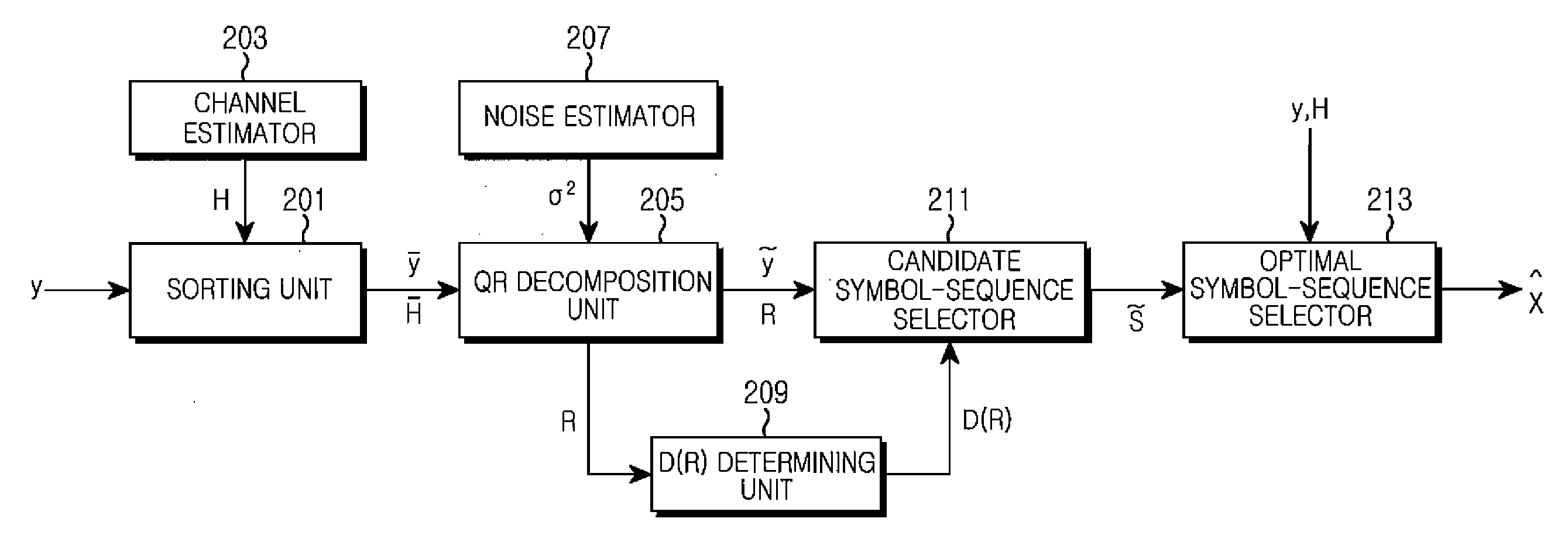
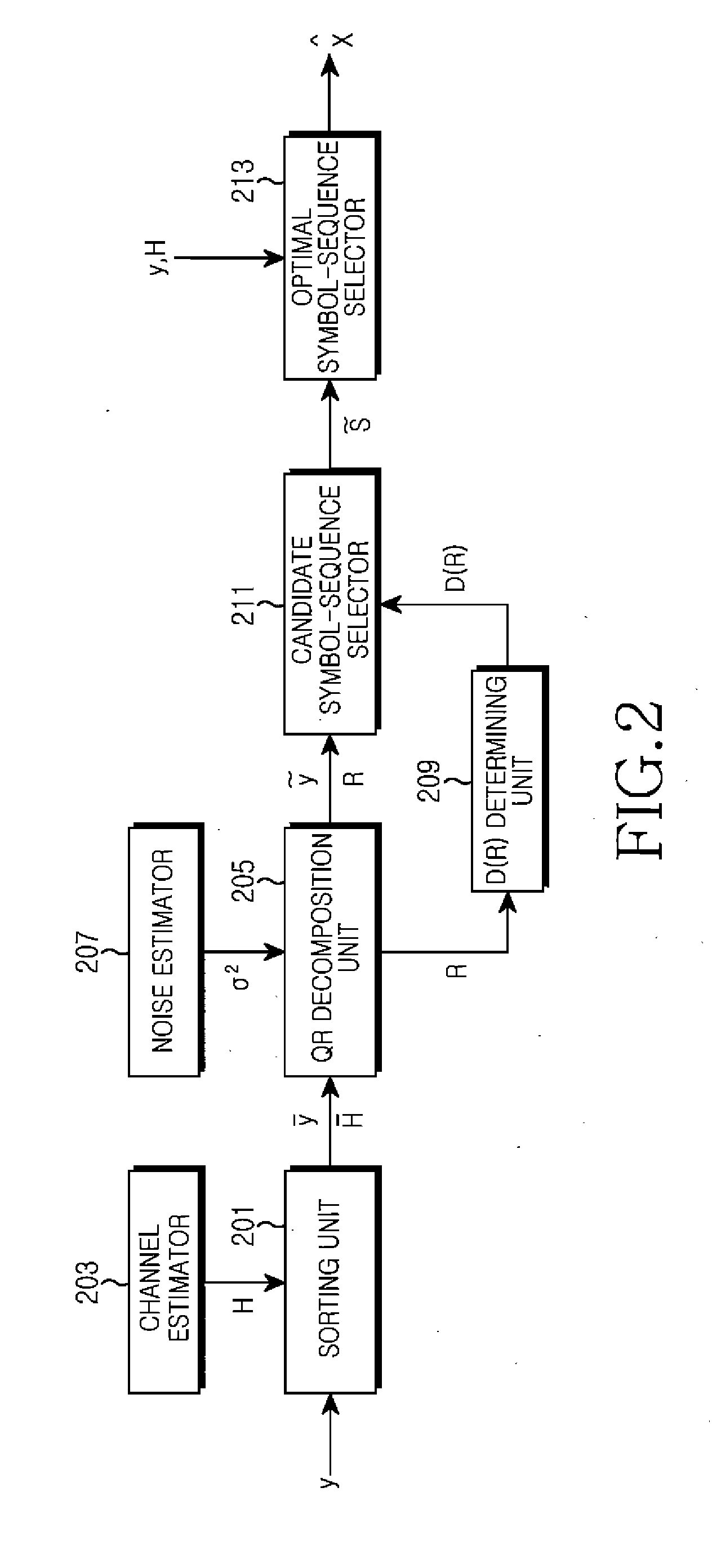
A signal detection apparatus and method using a modified stack algorithm in a Multi-Input Multi-Output (MIMO) system are provided. The signal detection method includes sorting signals received via antennas and channel coefficients for respective users in descending order, decomposing a channel matrix composed of the sorted channel coefficients into a unitary matrix and an upper-triangular matrix, determining the number of candidate symbol-sequences using the decomposed upper-triangular matrix, obtaining a signal vector for the antennas by using the sorted signals received via respective antennas and the unitary matrix, wherein the signal vector is proportional to the upper-triangular matrix, and detecting the determined number of candidate symbol-sequences by using a modified stack algorithm while expanding a stack structure for the obtained signal vector.

Description

JOINT RESEARCH AGREEMENT[0001]The claimed invention was made by, on behalf of, and / or in connection with one or more of the following parties to a joint research agreement: Research and Industrial Cooperation Group and Samsung Electronics Co., Ltd. The agreement was in effect on and before the date the claimed invention was made, and the claimed invention was made as a result of activities undertaken within the scope of the agreement.PRIORITY[0002]This application claims the benefit under 35 U.S.C. § 119(a) of a Korean patent application filed on Jun. 15, 2007 in the Korean Intellectual Property Office and assigned Serial No. 2006-53867, the entire disclosure of which is hereby incorporated by reference.BACKGROUND OF THE INVENTION[0003]1. Field of the Invention[0004]The present invention relates to a Multi-Input Multi-Output (MIMO) system. More particularly, the present invention relates to an apparatus and method for detecting a signal in a MIMO system.[0005]2. Description of the R...

Claims


Application Information

Patent Timeline
Patent Type & Authority Applications(United States)
IPC IPC(8): H04L1/02H03D1/00
CPCH04L25/03006H04L2025/03605H04L2025/03426H04B7/0842H04L1/0054H04L1/02
Inventor PARK, SUNG-WOOLEE, JOO-HYUNSUH, KYUNG-JOOKWON, YOUNG-HOONHWANG, SUNG-SOOKIM, JONG-INKANG, JOON-HYUKCHA, JONG-SUB
Owner SAMSUNG ELECTRONICS CO LTD
Why Eureka
Try Eureka