A Test System and Method of Operation

Inactive Publication Date: 2007-12-20
EMERSON NETWORK POWER EMBEDDED COMPUTING
View PDF13 Cites 12 Cited by
  • Summary
  • Abstract
  • Description
  • Claims
  • Application Information

AI Technical Summary

Benefits of technology

[0016]This feature may provide efficient and/or low complexity

Problems solved by technology

However, such an approach tends to be infle

Method used


Image

  • A Test System and Method of Operation
  • A Test System and Method of Operation
  • A Test System and Method of Operation

Examples


Embodiment Construction

[0025]The following description focuses on embodiments of the invention applicable to health monitoring and test reporting for a TCA hardware assembly. However, it will be appreciated that the invention is not limited to this application but may be applied to many other systems.

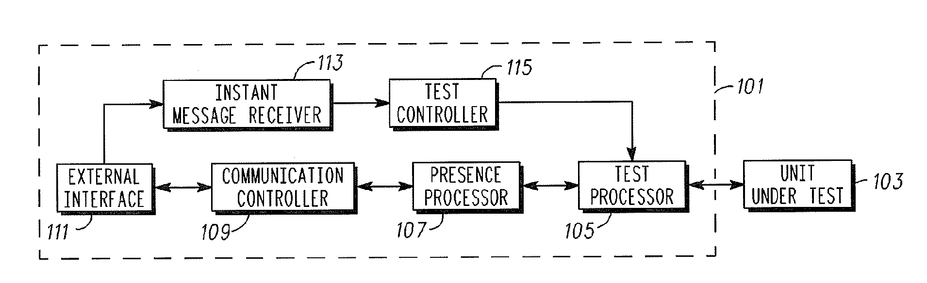
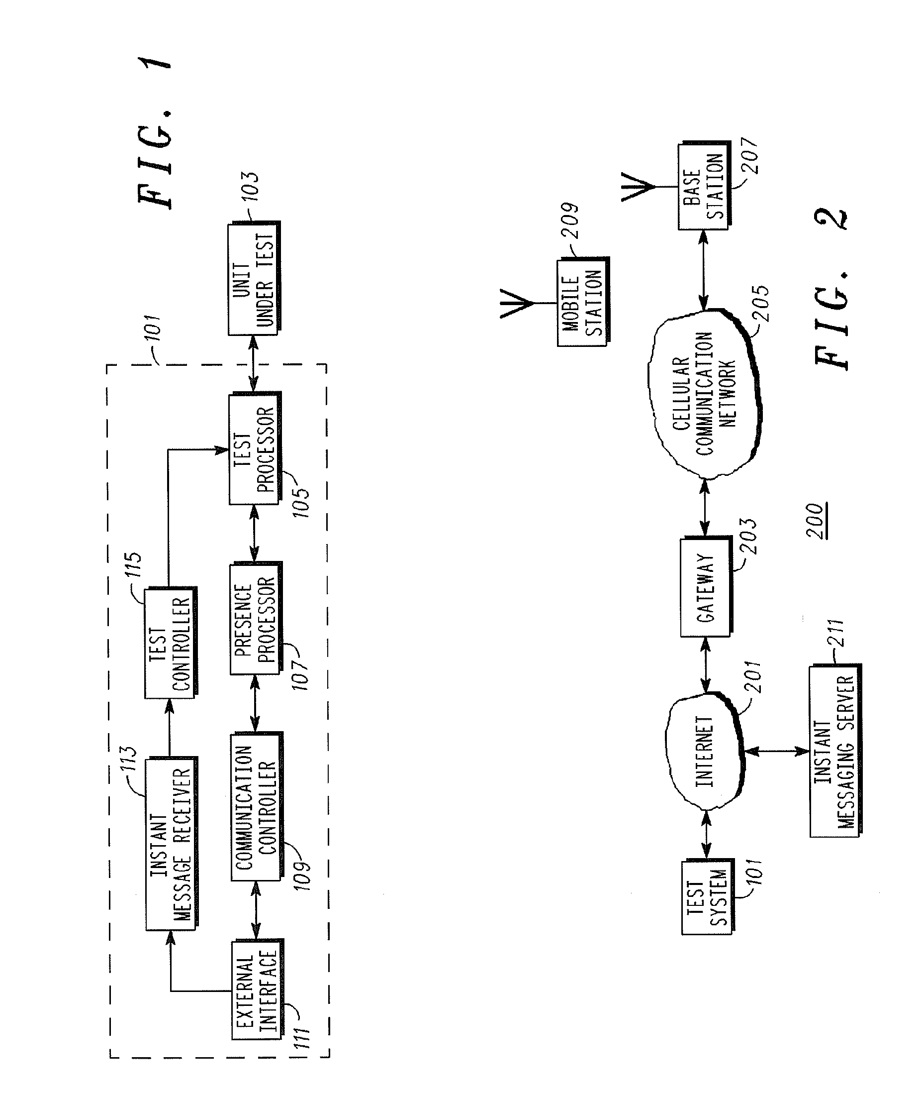
[0026]FIG. 1 illustrates a test system 101 in accordance with some embodiments of the invention. The test system 101 is in the specific example part of a TCA hardware assembly and is arranged to perform tests of subsystems of the TCA assembly such as of individual or groups of mezzanine cards, modules or blades.

[0027]In FIG. 1 a unit under test 103 is coupled to the test system 101 for testing. Although FIG. 1 illustrates only a single unit under test 103, it will be appreciated that the test system may be arranged to test a plurality of different modules, cards subsystems etc. Specifically, in different embodiments, the unit under test 103 may be considered to correspond to a single hardware element (e.g. a ...


PUM


Abstract

A test system comprises a test processor which determines an operational status, such as a fault status, for a unit under test. The unit under test may e.g. comprise one or more boards of an electronic assembly. A presence processor generates a presence message in response to the operational status where the presence message is in accordance with a user presence message protocol. A communication controller then transmits the presence message to a remote network element of a communication network. The remote network element may be a presence server which can transmit a presence status update to associated devices. The invention may allow efficient and remote status monitoring for a test system using user presence infrastructure.

Description

FIELD OF THE INVENTION[0001]The invention relates to a test system and method of operation and in particular, but not exclusively, to hardware level testing of electronic assemblies.BACKGROUND OF THE INVENTION[0002]In order to facilitate and reduce the cost of implementation of complex electronic equipment, there is an increasing drive towards interoperability between different manufacturers. Furthermore, testability of electronic assemblies is becoming increasingly important in order to ensure high reliability and early fault detection.[0003]Specifically, in order to facilitate implementation of hardware for telecommunication applications, the PCI Industrial Computer Manufacturers Group (PICMG™) has developed hardware standards known as Telecom Computing Architecture (TCA) standards. The standards define a number of parameters such as mechanical features (e.g. rack size, board size), electrical features (e.g. supply voltages, max power consumptions) and interworking features (e.g. ...

Claims


Application Information

Patent Timeline
IPC IPC(8): H04M1/24H04M3/08H04M3/22
CPCH04L41/046H04L43/0817H04L65/1006H04L67/24H04Q3/0087H04L65/1104H04L67/54
Inventor HALLIDAY, DAVID J.LAKIN, STEVE J.
Owner EMERSON NETWORK POWER EMBEDDED COMPUTING
Why Eureka
Try Eureka