Interventional MR imaging with detection and display of device position

a technology of magnetic resonance imaging and position detection, applied in the field of magnetic resonance imaging system, can solve the problems of positional detection of a device, difficulty in providing an operator with an accurate position of the device tip, and foregoing conventional techniques have encountered various difficulties, so as to facilitate the confirmation of necessary items

Inactive Publication Date: 2005-11-01
TOSHIBA MEDICAL SYST CORP
View PDF18 Cites 33 Cited by
  • Summary
  • Abstract
  • Description
  • Claims
  • Application Information

AI Technical Summary

Benefits of technology

[0033]Thus, information indicative of a paracentesis plan such as a needling start position is actually indicated on the body surface of an object. This indication is performed by for example a light projector that projects light onto the body surface of an object. This enables an operator to easily confirm necessary items for paracentesis, such as a target to be needled, a needling start position, and a needling path, by viewing the projected information on the object's body surface to be handled actually, thus enabling the operator to understand it well.
[0034]According to the present invention, an operation (interventional MRI) can be performed under the guidance of MR imaging on the basis of a preoperative plan established as above. In response to necessity, or, at any time, MR imaging can be performed during the operation. In the case of an operation on MR imaging, compared to an operation on X-CT imaging, there are advantages that there is no worry about X-ray exposure and imaging can be done timely on the spot to confirm operational progress states and an object's lesion. In the case of the interventional MRI, differently from the X-CT, functional information as well as ordinal contour information can be acquired during the operation, with the result that functions or others of an organ can be confirmed on the spot.

Problems solved by technology

However, the foregoing conventional techniques have encountered various difficulties as follows.
First, there are problems concerning positional detection of a device such as a catheter.
Since the positional detection according to the conventional ordinary imaging is based on the technique of imaging indirectly influence of a device on a magnetic field, it was difficult to provide an operator with an accurate position of the device tip.
This is because the contour, positional shifts and / or intensity of the device on images are changed depending on imaging techniques; position, direction and material of a catheter; and imaging directions Further, because a pulse sequence for imaging is used to recognize a device position, recognizing the position at a time instant always requires a period of time needed for one time of ordinary imaging, This results in a problem that resolution to display the position of the device tip is still lower.
A second problem derives from the conventional technique of attaching an RF reception coil on the tip of a device such as a catheter.
This technique was unfavorable to the observation of the entire device.
It was also difficult to grasp a direction along which the device is currently oriented and a direction along which the device should be needled from now on.
Additionally, in this case, a slight spatial deviation of the catheter tip, which occurs due to hand shaking, makes it difficult to precisely recognize the tip spatial position.
A third problem relates to the technique of attaching a plurality of RF reception coils on the device.
In this configuration, it is necessary to perform the positional detection for each of the plural RF reception coils, This makes the entire system complicated and it takes time to measure the positions of the coils.
Second, there are problems concerning monitoring needled states of a device such as a catheter.
A first drawback is concerned with a reference section (that is, an imaged section containing both a needling start position and a target) acquired before starting the paracentesis.
Such shifts become obstacles to a smooth needling along a scheduled path, requiring a great deal of time and work in the needling operation.
This may cause trouble in treatment and examination.
A second drawback will be caused when an operator inserts a puncture needle in a direction different from the reference section.
If such an insertion is done, the needle tip deviates from the reference section, thus failing to display the tip on images.
Hence the conventional monitoring technique was not suitable for needling operations involving subtle operations.
A third problem arises due to an interval between a preoperative plan and an actual treatment.
Hence, in performing the actual paracentesis, it takes much time for an operator to understand positional relationships about the needling start position and needling path based on the plan.
This results in a lowered patient's throughput and frequently generates the situation where needling results in different ones from the planned needling start position and planned path.

Method used


Image

  • Interventional MR imaging with detection and display of device position
  • Interventional MR imaging with detection and display of device position
  • Interventional MR imaging with detection and display of device position

Examples


first embodiment

[0060](First Embodiment)

[0061]Referring to FIGS. 1 to 4, a first embodiment of the present invention will now be described.

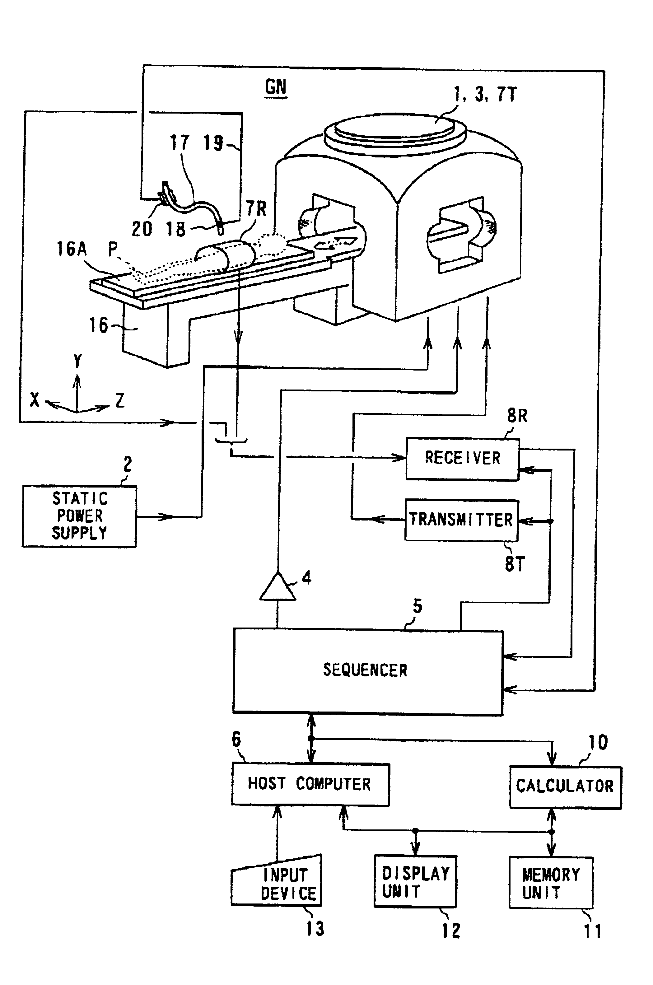
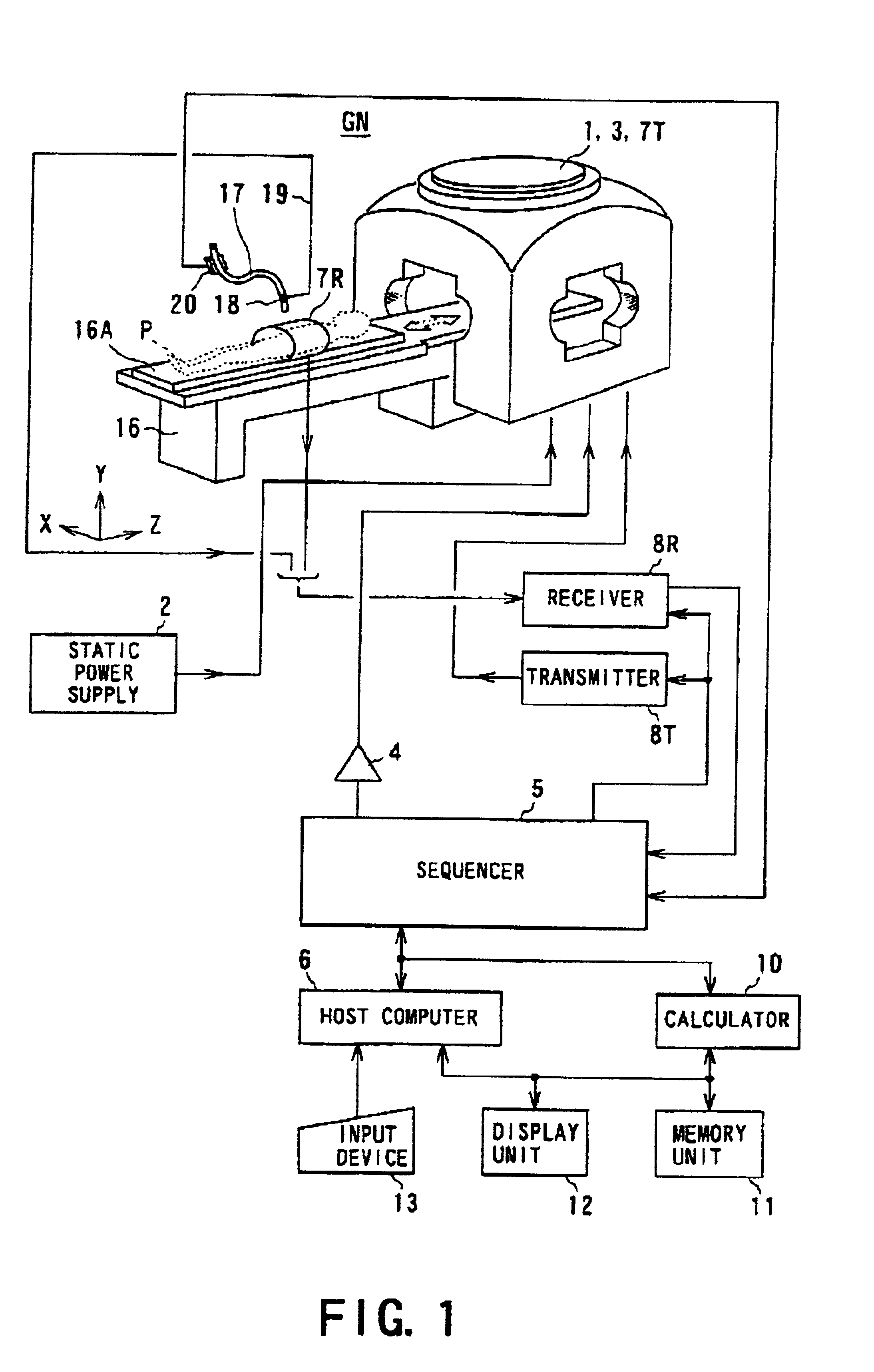
[0062]A magnetic resonance imaging system according to the present embodiment is constructed as, what we call, an open type of system. This open type of system provides an easier access to an object, which is therefore suitable for interventional MRI.

[0063]An outlined configuration of this magnetic resonance imaging system is shown in FIG. 1. The magnetic resonance imaging system is equipped with an open type of gantry GN in which a patient handles as the object is placed within a static magnetic field. This gantry GN has a magnet 1 for the static magnetic field, which is constructed by laterally arranged magnets such as superconducting magnets, and four pillars for support the magnets. The static magnet 1 has two pairs of disc-like magnets, each pair being placed in an upper or lower structure thereof, thus providing a diagnostic spacing between the upper and l...

second embodiment

[0096](Second Embodiment)

[0097]Referring to FIG. 8, a second embodiment will now be described. The magnetic resonance imaging system used by this present embodiment is also applied to the interventional MRI. The constituents of this system are identical or similar to those in the first embodiment, so the same references are adopted to omit their detailed explanations.

[0098]The processing executed by the present embodiment is concerned with tracking of a catheter, i.e., a representative of various devices, that has been inserted into an object.

[0099]As described in the foregoing first embodiment, when the tip of the catheter under operations is tracked with use of a minute RF detection coil (micro coil), only a small area (spot-like area) obtained by processing signals acquired from the RF detection coil is depicted as tracking loci. However, the depiction of such a small area is unsatisfactory for a full understanding of positional relationships between the catheter tip and surround...

third embodiment

[0107](Third Embodiment)

[0108]Referring to FIGS. 9 to 10, a third embodiment will now be described.

[0109]The magnetic resonance imaging system according to the present embodiment is directed to the interventional MRI capable of automatically tracking a cross section to be imaged to a puncture needle serving as a device.

[0110]An outlined configuration of the magnetic resonance imaging (MRI) system is shown in FIG. 9.

[0111]The magnetic resonance imaging system has a gantry 51 for generating a static magnetic field in which a patient as the object is placed. The gantry 51 includes a static field magnet 52 composed of for example a superconducting magnet. A diagnostic region of which magnetic intensity is uniform is in part formed of the static field generated by the magnet 52. For the magnet 52 formed in an approximately cylinder, a patient is located partly and entirely within the diagnostic region with the patient laid on a not-shown couch. In the case that the magnet 52 is an open t...


PUM


Abstract

A magnetic resonance imaging system for interventional MR imaging involves operations to insert a device such as a catheter into an object. According to the system, a tip position of the catheter is detected, data indicative of moved loci of the catheter are produced from data indicative of the detected tip position, and the produced movement locus data are displayed. In addition, even when an operator changes the progress direction of the device such as a puncture needle, an imaging cross-section automatically tracks movements of the device. Appropriate preoperative planning is also provided.

Description

BACKGROUND OF THE INVENTION[0001]1. Technical Field of the Invention[0002]The present invention relates to a magnetic resonance imaging system capable of performing imaging known as interventional MRI (magnetic resonance imaging).[0003]2. Related Art[0004]Magnetic resonance imaging uses a radio frequency signal of a Larmor frequency to magnetically excite nuclear spins of an object to be imaged placed in a uniform static magnetic field. An MR signal resulting from the excitation is used to reconstruct an image.[0005]Recently, the magnetic resonance imaging has been used in various medical fields. One such use is a treatment or examination to perform paracentesis with a puncture needle inserted from outside the body, operations of a catheter, surgery, and others with magnetic resonance imaging performed or under the state in which the magnetic resonance imaging can be performed. Such magnetic resonance imaging is called as interventional MRI, which has drawn much attention recently.[...

Claims


Application Information

Patent Timeline
Patent Type & Authority Patents(United States)
IPC IPC(8): G01R33/28
CPCG01R33/287
Inventor HOSHINO, TSUTOMUKUHARA, SHIGEHIDEYAMAGATA, HITOSHIKASSAI, YOSHIMORI
Owner TOSHIBA MEDICAL SYST CORP
Why Eureka
Try Eureka