
Sound image control apparatus and sound image control method

a control apparatus and sound image technology, applied in electrical devices, stereophonic arrangments, pseudo-stereo systems, etc., can solve the problems of increasing the operation amount, the need for enormous amounts of transmission characteristic filters, and the circuit scale of the sound image control section for controlling the sound image increases, so as to achieve the effect of increasing the accuracy of sound image localization

Inactive Publication Date: 2007-12-20
SOCIONEXT INC
View PDF12 Cites 21 Cited by
  • Summary
  • Abstract
  • Description
  • Claims
  • Application Information

AI Technical Summary

Benefits of technology

[0021]It is therefore an object of the present invention to provide a sound image control apparatus and sound image control method capable of increasing accuracy of sound image localization in a distance direction while keeping fixed intervals of transmission characteristic filters, without increasing the number of the transmission characteristic filters.

Problems solved by technology

In such a conventional sound image control apparatus, it is expected to reduce the data amount to some extent, but transmission characteristic filters are not prepared at fixed intervals, and therefore the control method becomes complicated when selecting a transmission characteristic filter in the vicinity of a coordinate point of a move destination calculated from a move instruction for controlling the sound image, and there is a problem that the circuit scale of the sound image control section for controlling the sound image increases, and the operation amount increases.
Further, for the distance direction, it is necessary to prepare transmission characteristic filters in all directions for each distance, and therefore, in order to increase the accuracy in the distance direction, transmission characteristic filters corresponding to all directions are required for one distance and there is a problem that an enormous amount of transmission characteristic filters are required.

Method used


Image

  • Sound image control apparatus and sound image control method
  • Sound image control apparatus and sound image control method
  • Sound image control apparatus and sound image control method

Examples


Embodiment Construction

[0033]An embodiment of the present invention will be described in detail below with reference to the accompanying drawings.

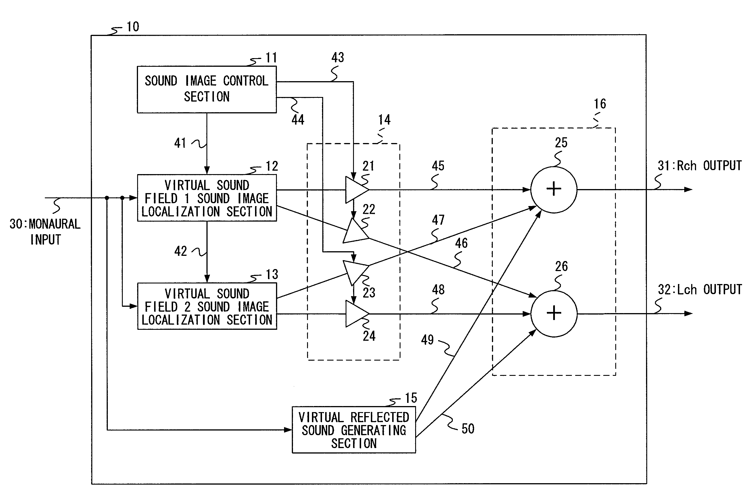
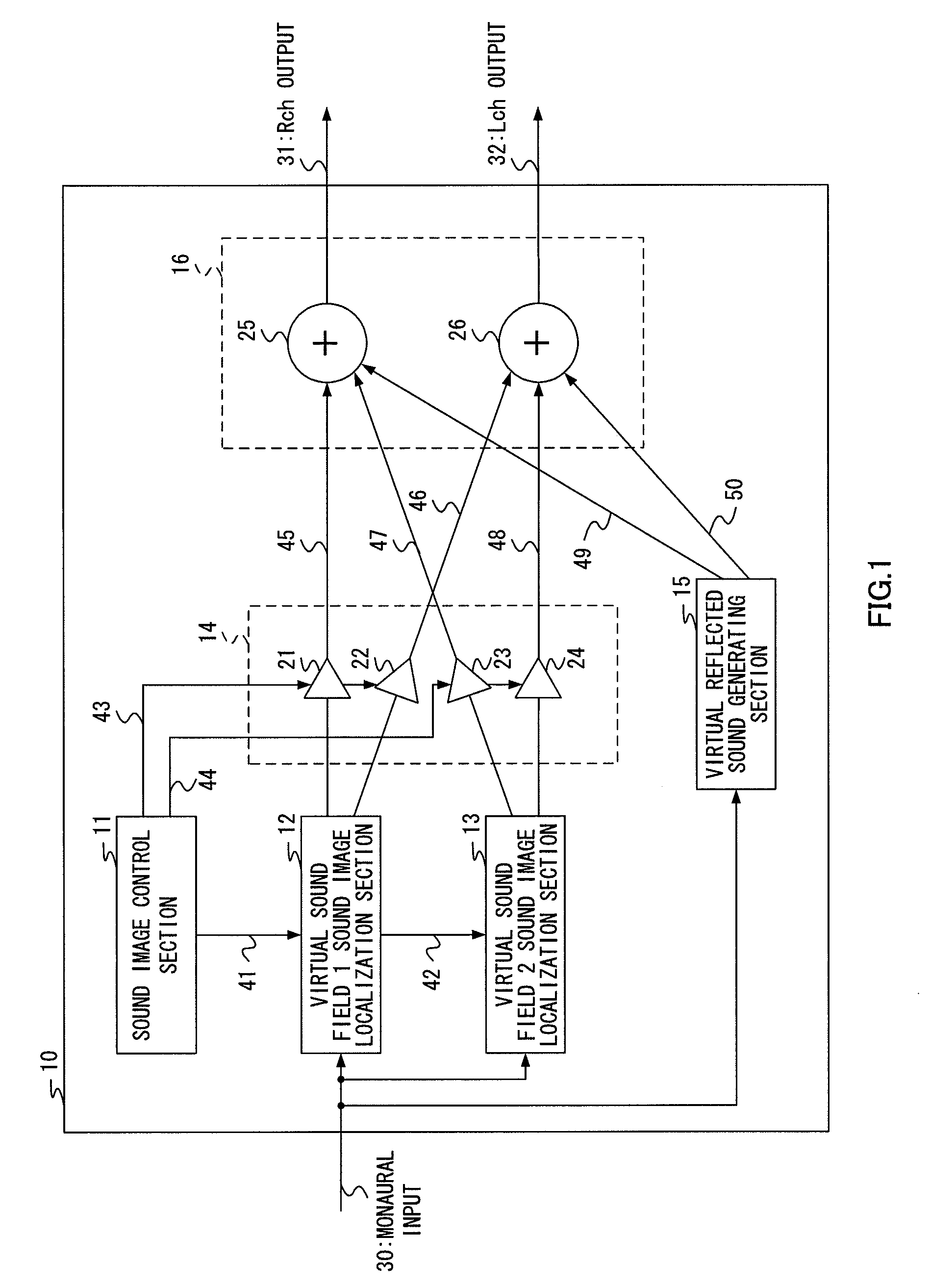
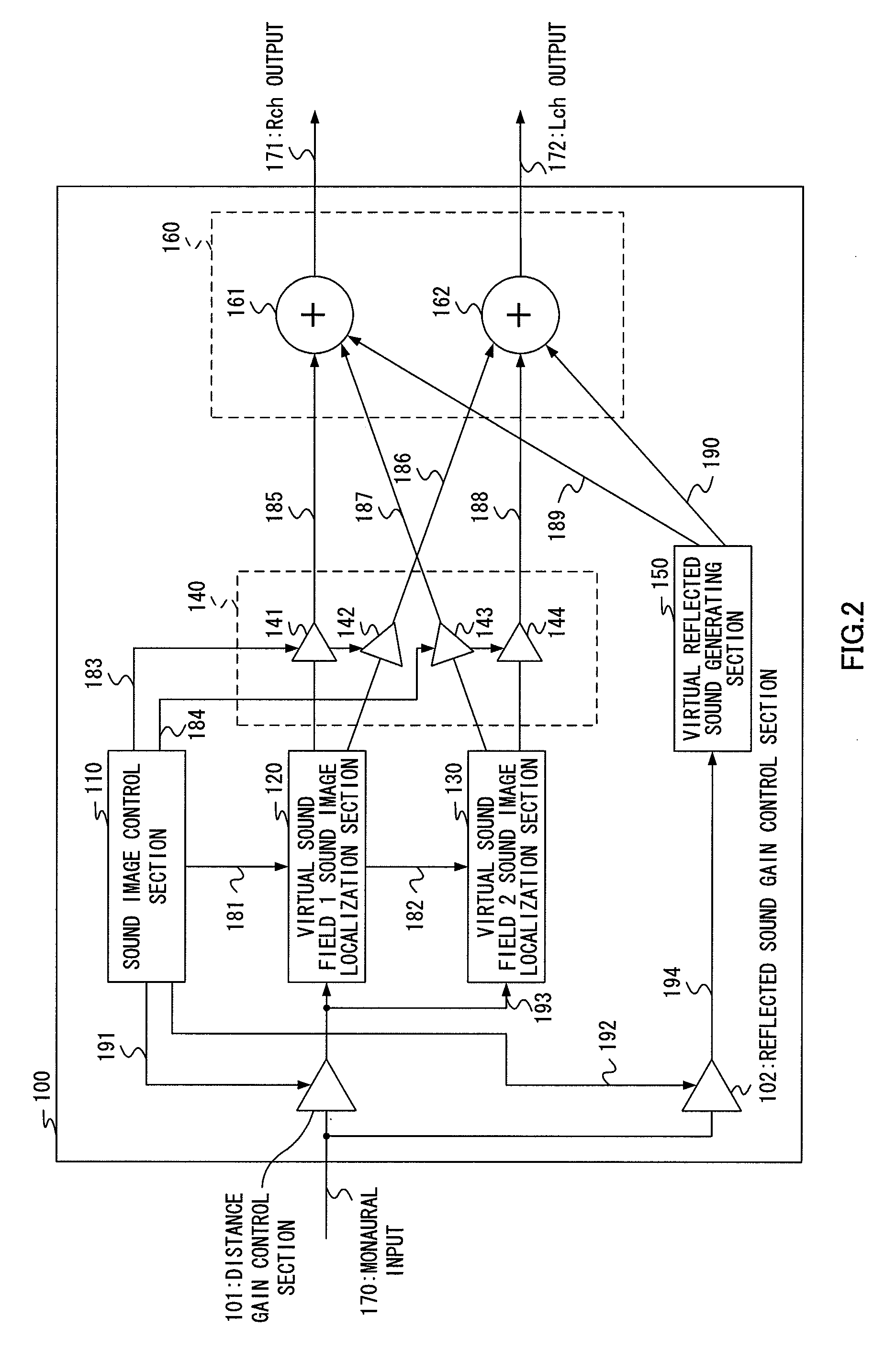
[0034]FIG. 2 is a block diagram showing a configuration of the sound image control apparatus according to one embodiment of the present invention. This embodiment describes an example where the present invention is applied to a sound image control apparatus that localizes a sound image in an arbitrary position around a listener using stereo audio signals of two channels.

[0035]In FIG. 2, sound image control apparatus 100 is configured with distance gain control section 101, reflected sound gain control section 102, sound image control section 110, virtual sound field 1 sound image localization section 120, virtual sound field 2 sound image localization section 130, Panning Gain control section 140, virtual reflected sound generating section 150 and localized sound / virtual reflected sound adding section 160.

[0036]Panning Gain control section 140 is configured with...


PUM


Abstract

A sound image control apparatus and sound image control method capable of increasing the accuracy, in particular, in the distance direction while keeping fixed intervals of transmission characteristic filters, without increasing the number of the transmission characteristic filters. Sound image control apparatus 100 is provided with distance gain control section 101 that performs gain control of the sound pressure of an input monaural audio signal of one channel in the distance direction from a head to a sound image before input to virtual sound field 1 sound image localization section 120 and virtual sound field 2 sound image localization section 130, and reflected sound gain control section 102 that performs gain control by distance of a reflected sound of the sound pressure of the input monaural audio signal of one channel before input to virtual reflected sound generating section 150 that controls the sound image to be localized outside the head when the sound is listened to with headphones.

Description

CROSS REFERENCE TO RELATED APPLICATIONS[0001]The disclosure of Japanese Patent Application No. 2006-164884 filed on Jun. 14, 2006 including the specification, drawings and abstract is incorporated herein by reference in its entirety.BACKGROUND OF THE INVENTION[0002]1. Field of the Invention[0003]The present invention relates to a sound image control apparatus and sound image control method for reproducing a transmission characteristic using a digital filter and convolving the transmission characteristic in an original sound (hereinafter, referred to as a source sound), and thereby controlling sound image localization.[0004]2. Description of Related Art[0005]There is a sound image control apparatus which uses a fact that the transmission characteristic changes due to influence of the shape of head and auricles according to the direction of a sound source position when a human catches a sound, reproduces a transmission characteristic using a digital filter and convolves the transmissi...

Claims


Application Information

Patent Timeline
Patent Type & Authority Applications(United States)
IPC IPC(8): H04R5/00
CPCH04S1/002H04S5/00H04S2400/13H04S2400/11H04S7/30H04S3/00
Inventor IMAKI, SHUNSAKU
Owner SOCIONEXT INC
Learn More