
Optical Re-Modulation in DWDM Radio-Over-Fiber Network

a fiber optic network and optical remodulation technology, applied in electromagnetic transmission, electrical equipment, transmission, etc., can solve problems such as signal interference with each other, and achieve the effect of reducing interference between wireless transmissions

Inactive Publication Date: 2007-12-20
NEC LAB AMERICA
View PDF1 Cites 108 Cited by
  • Summary
  • Abstract
  • Description
  • Claims
  • Application Information

AI Technical Summary

Benefits of technology

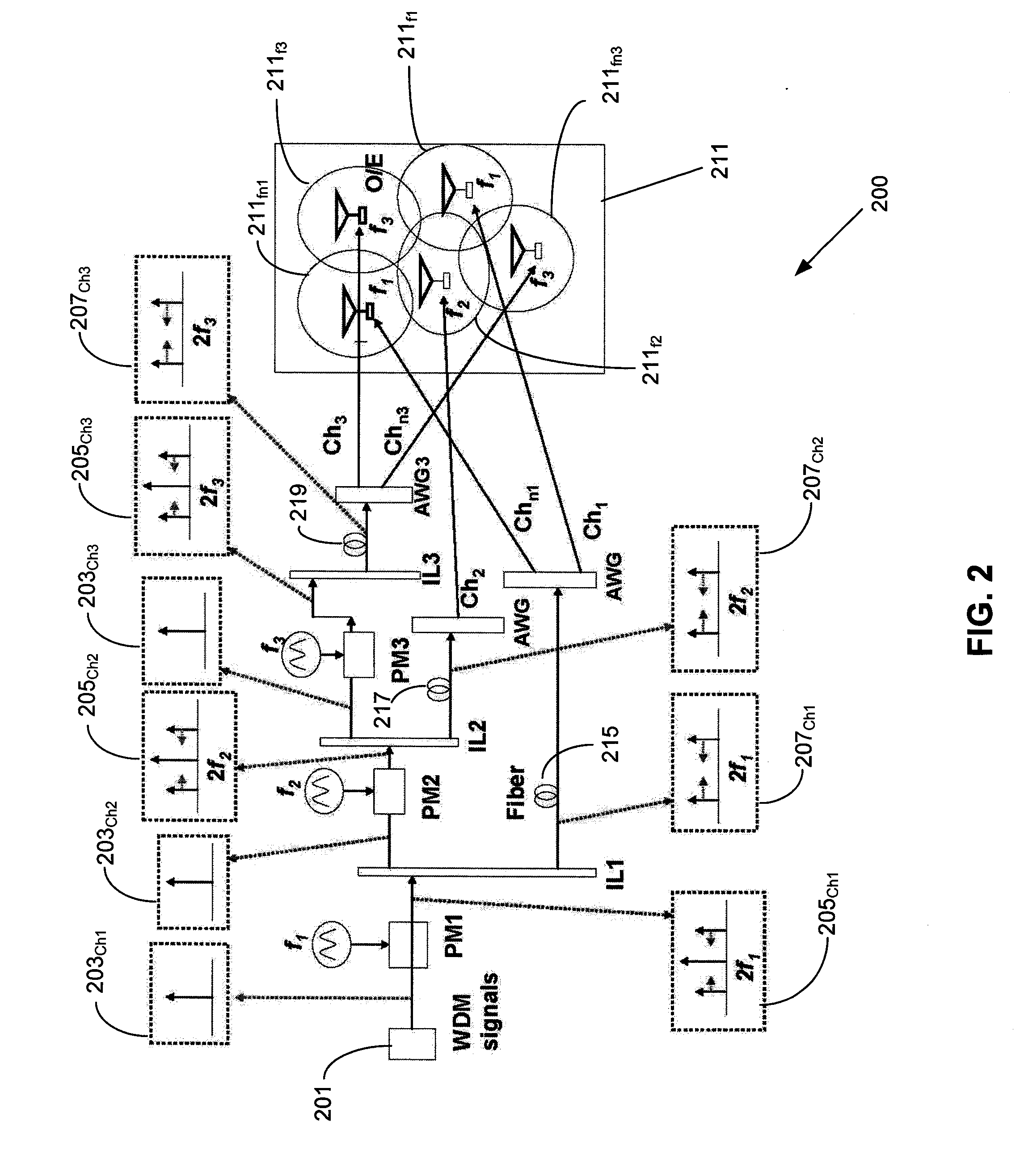
[0006] In accordance with the invention, an apparatus includes multiple signal paths for optically converting an optical signal to multiples of said optical signal at different respective carrier frequencies for reducing interference between wireless transmissions of said multiples of said optical signal. In a preferred embodiment, the converting includes a first modulator for modulating the optical signal into a first optical carrier and an initial first-order sideband signal with a frequency spacing twice that of the first optical carrier and a first interleaver for separating the first optical carrier and the initial first-order sideband signal. The converting also includes a second phase modulator for modulating the first optical carrier into a second optical carrier and a second first-order sideband signal with a frequency spacing twice that of the second optical carrier.
[0007] In another aspect of the invention, a method includes optically converting an optical signal to multiples of said optical signal at different respective carrier frequencies for reducing interference between wireless transmissions of said multiples of said optical signal. Preferably, the converting includes modulating the optical signal into a first optical carrier and an initial first-order sideband signal with a frequency spacing twice that of the first optical carrier and separating the first optical carrier and the initial first-order sideband signal. The method further includes converting modulating the first optical carrier into a second optical carrier and a second first-order sideband signal with a frequency spacing twice that of the second optical carrier.

Problems solved by technology

After down-conversion, these signals would interfere with each other when the customer unit receives them.

Method used


Image

  • Optical Re-Modulation in DWDM Radio-Over-Fiber Network
  • Optical Re-Modulation in DWDM Radio-Over-Fiber Network
  • Optical Re-Modulation in DWDM Radio-Over-Fiber Network

Examples


Embodiment Construction

[0015] The schematic 200 of FIG. 2 shows an exemplary embodiment of an inventive all optical carrier re-modulation to different carrier frequencies for reducing the physical layer interference in overlapped transmission regions. A phase modulation PM1, PM2, PM3 is used along with interleaving IL1, IL2, IL3 to realize the DWDM signal up-conversion. After modulation of the incoming optical signal carrier 203ch1, 203ch2, 203ch3 driven by a small RF signal with frequency f1, f2, f3 the optical spectrum of each channel contains an optical carrier and the first order sideband signal 205ch1, 205ch2, 205ch3 with a respective frequency spacing 2f1, 2f2, 2f3 as shown in FIG. 2. Then an interleaver IL1, IL2 is used to separate out the remaining optical carrier 203ch2, 203ch3 and the first-order sideband signal 207ch1, 207ch2, 207ch3. At the final wireless transmission stage 211, with optical-to-electrical conversions 211f1, 211f2, 211f3, 211fn1, 211fn3 where the re-modulated signals are transm...


PUM


Abstract

An apparatus includes multiple signal paths for optically converting an optical signal to multiples of the optical signal at different respective carrier frequencies for reducing interference between wireless transmissions of the multiples of the optical signal. Preferably, the converting includes a first modulator for modulating the optical signal into a first optical carrier and an initial first-order sideband signal with a frequency spacing twice that of the first optical carrier and a first interleaver for separating the first optical carrier and the initial first-order sideband signal. The converting also includes a second phase modulator for modulating the first optical carrier into a second optical carrier and a second first-order sideband signal with a frequency spacing twice that of the second optical carrier.

Description

[0001] This application claims the benefit of U.S. Provisional Application No. 60 / 804,666, entitled “Reduction of Physical layer Interference in a DWDM Radio Over Fiber Network by using Multiple Time Remodulation”, filed on Jun. 14, 2006, the contents of which is incorporated by reference herein.BACKGROUND OF THE INVENTION [0002] The present invention relates generally to optical communications, and, more particularly, to reduction of physical layer interference in dense wavelength division multiplexing DWDM radio-over-fiber network by using multiple time re-modulation. [0003] The application of radio-over-fiber (ROF) for broadband wireless access has attracted much attention recently because it provides the mobile broadband services, wireless local area networks LANs, and fixed wireless access services such as Local Multipoint Distribution Service LMDS that uses microwave signals to transmit and receive data. A few key issues such as all-optical up-conversion, down-conversion and n...

Claims


Application Information

Patent Timeline
IPC IPC(8): H04B10/04
CPCH04B10/25754
Inventor YU, JIANJUNXU, LEIWANG, TING
Owner NEC LAB AMERICA
Learn More