Rotor blade for a compressor or a gas turbine

a technology for compressors and gas turbines, applied in the direction of machines/engines, mechanical equipment, sustainable transportation, etc., can solve the problems and achieve the effect of increasing the lifetime of the latter and reducing the stress

Active Publication Date: 2007-12-20
SN DETUDE & DE CONSTR DE MOTEURS DAVIATION S N E C M A
View PDF3 Cites 10 Cited by
  • Summary
  • Abstract
  • Description
  • Claims
  • Application Information

AI Technical Summary

Benefits of technology

[0009] For this purpose, the invention proposes a rotor or stator blade for a compressor or a gas turbine, comprising a convex outer surface or suction side and a concave inner surface or pressure side, which are joined at their upstream ends by a leading edge and at their downstream ends by a trailing edge for the gases, a platform connecting the suction side and the pressure side to a blade root, and at least one stiffener formed by a flat web of material joining the downstream part of the platform to the blade root, this stiffener extending perpendicular to the platform and transversely or circumferentially with respect to the axis of the rotor, wherein, to reduce the stresses in the joint region where the trailing edge joins the platform, the stiffener includes at least one notch or cut-away formed substantially level with the trailing edge.
[0010] This notch or cut-away, formed level with the trailing edge, gives the stiffener, and therefore the platform, relative flexibility in this region, which thereby allows them to deform slightly and to follow the deformation of the trailing edge when the blade is subjected to the centrifugal forces. This results in a substantial reduction in the stresses in the joint region between the aerofoil and the platform of the blade and increases the lifetime of the latter.
[0015] In operation, that end of the stiffener which lies in line with the trailing edge forms a mass, which is deformed at the same time as the pressure and suction sides of the blade. This makes it possible for the downstream part of the platform to deform more easily and to better follow the deformation of the pressure and suction sides, and therefore to further limit the stresses in the region where they join the platform.

Problems solved by technology

This results in a substantial reduction in the stresses in the joint region between the aerofoil and the platform of the blade and increases the lifetime of the latter.

Method used


Image

  • Rotor blade for a compressor or a gas turbine
  • Rotor blade for a compressor or a gas turbine
  • Rotor blade for a compressor or a gas turbine

Examples


first embodiment

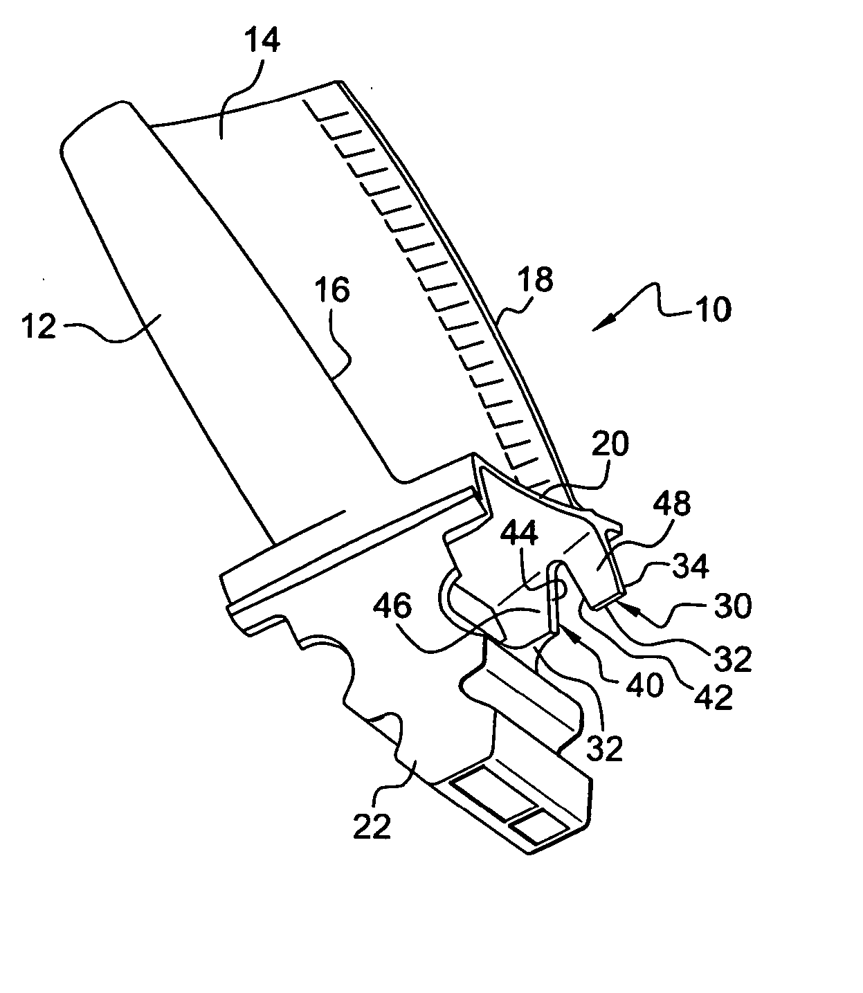
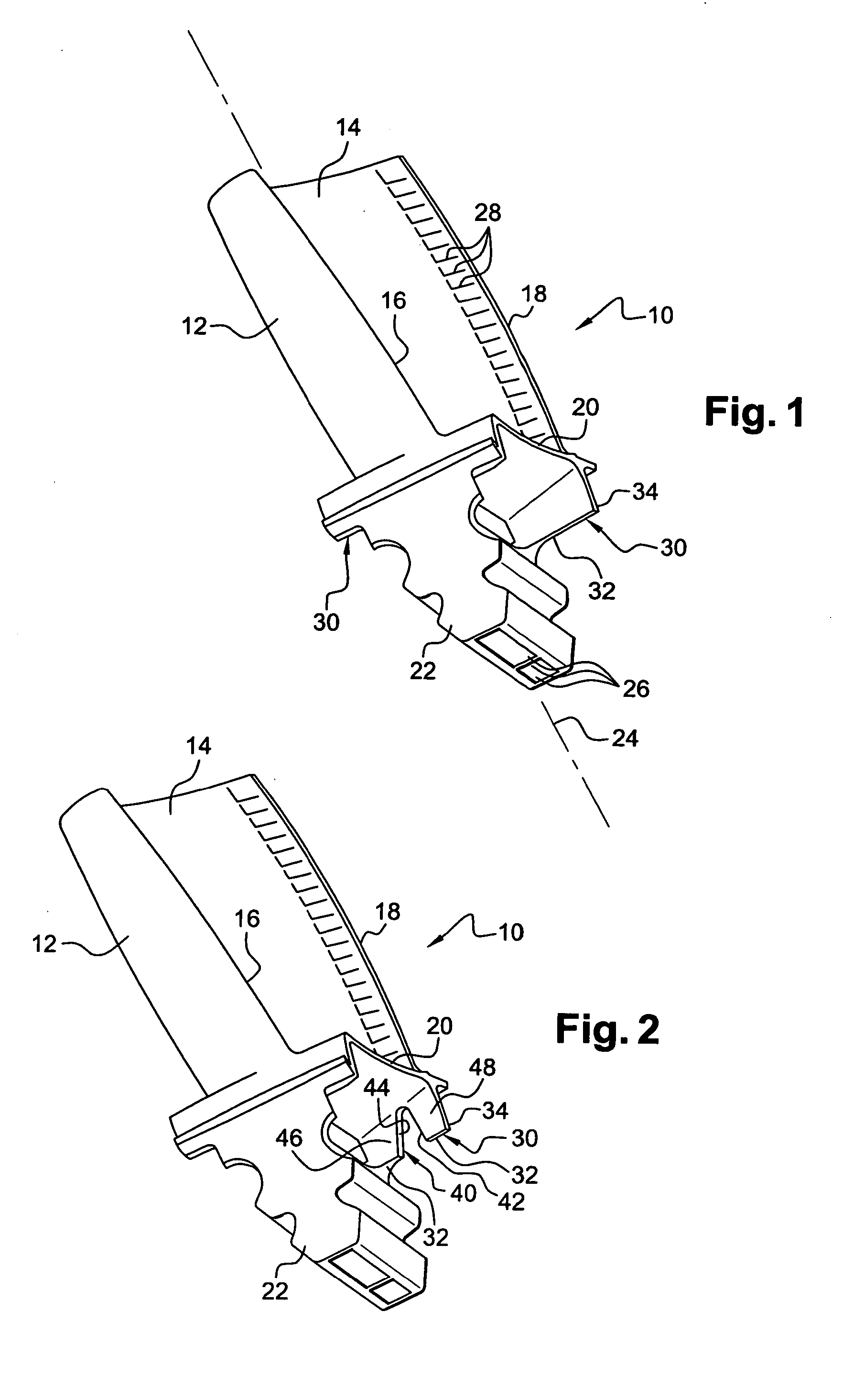
[0038]FIG. 2 shows the invention, in which the stiffener 30 includes a notch 40 that extends from its radially internal edge 32 as far as a point close to the platform 20. This notch may have any shape, with straight, oblique or curved edges. In the example shown, this notch 40 has substantially the shape of an inverted V and has an edge 42, approximately perpendicular to the platform 20 and parallel to the lateral end edge 34 of the stiffener 30, and an edge 44 which is oblique to the platform 20 and connects the upper end of the edge 42 near the platform 20 to the radially internal edge 32 of the stiffener 30.

[0039] The stiffener 30 therefore comprises two separate parts, namely a part 46, which joins the platform 20 to the blade root 22 and is intended to stiffen the platform 20, and another part 48 located at the end of the stiffener 30 beneath the joint region where the trailing edge 18 joins the platform 20 and capable of deforming when it is subjected to the centrifugal force...

second embodiment

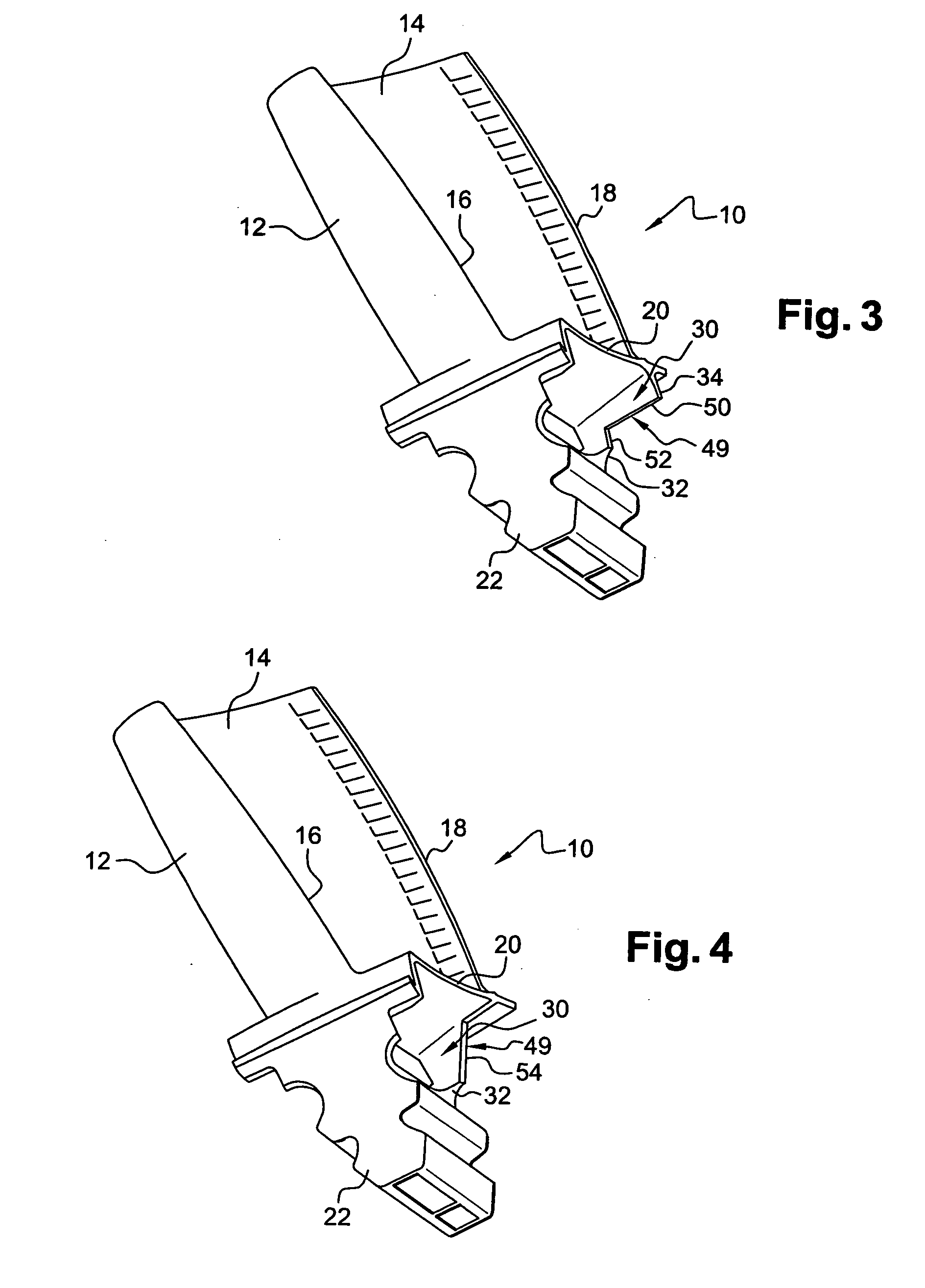
[0040]FIG. 3 shows the invention, in which the lateral edge 34 of the stiffener 30 joined to the edge of the platform 20 includes a cut-away 49 which extends over part of the height of the stiffener 30 from its radially internal edge 32 and over a fraction of the length of the stiffener 30 in the transverse or circumferential direction. This cut-away may have any shape, with straight, oblique or curved edges. In this example, the stiffener 30 has substantially the form of a L with an edge 50, parallel to the platform 20 and joined to the remaining part of the lateral edge 34 of the stiffener 30, and with a straight or oblique edge 52, which is joined to the remaining part of the radially internal edge 32 of the stiffener 30.

[0041] The cut-away 49 of the stiffener 30 makes it possible for the downstream part of the platform 20 lying beneath the trailing edge 18 to deform when the compressor or turbine is in operation and reduces the loads exerted on the region where it joins the plat...


PUM


Abstract

Rotor blade for a compressor or a gas turbine, in particular for a turbojet engine, comprising a suction side and a pressure side, which are joined at their upstream ends by a leading edge and at their downstream ends by a trailing edge for the gases, a platform connecting the suction side and the pressure side to a blade root, and a stiffener formed beneath the downstream part of the platform and including at least one notch or a cut-away in line with the trailing edge, in order to reduce the stresses in the joint region between the aerofoil and the platform.

Description

[0001] The present invention relates to a rotor or stator blade for a compressor or a gas turbine, and to a turbojet or industrial compressor or turbine comprising a plurality of these blades. BACKGROUND OF THE INVENTION [0002] A rotor or stator blade for a compressor or a gas turbine has a convex outer surface or suction side and a concave inner surface or pressure side, which are joined at their upstream ends by a leading edge and at their downstream ends by a trailing edge for the gases. The pressure side and the suction side are attached to a platform, which is provided with a blade root of the dovetail, fir-tree or similar type, intended to be inserted into a corresponding cavity in a rotor disc of the compressor or the gas turbine. [0003] A lateral reinforcing web called a “stiffener” is formed beneath the platform, between an inner surface of the latter and a lateral surface of the blade root, and extends transversely beneath a downstream part of the platform. If necessary, a...

Claims


Application Information

Patent Timeline
Patent Type & Authority Applications(United States)
IPC IPC(8): F01D11/00F01D5/14
CPCF01D5/147F05D2260/94F05D2240/80Y02T50/671F05D2260/941Y02T50/60
Inventor BIL, ERIC STEPHANGIOT, CHANTAL GISELESCHLESINGER, THOMAS
Owner SN DETUDE & DE CONSTR DE MOTEURS DAVIATION S N E C M A
Why Eureka
Try Eureka