Battery Apparatus with Heat Absorbing Body

a battery apparatus and body technology, applied in the direction of current conducting connection, cell components, grouping of flat cells, etc., can solve the problems of reducing the heat dissipation area affecting and affecting the use of the battery apparatus. , to achieve the effect of prolonging the life of the battery apparatus

Inactive Publication Date: 2007-12-20
AMITA TECH
View PDF6 Cites 56 Cited by
  • Summary
  • Abstract
  • Description
  • Claims
  • Application Information

AI Technical Summary

Benefits of technology

[0008]Therefore, the present invention is to overcome the shortcomings of the prior art by providing a battery apparatus with a heat absorbing body that installs and attaches a heat absorbing body onto the exterior of cells, so that a phase change material in the heat absorbing body can absorb the heat released by the cells to maintain the operations at a permitted operating temperature and extending the life of use of the battery apparatus.

Problems solved by technology

However, such electric appliances and equipments require a power recharge function.
Since the output of the electric power is in form of a short-duration high current, each cell results in a high temperature easily and it is an important issue for manufacturers to find a way to solve the heat dissipation problem of the cells.
Although traditional battery apparatuses may come with slight heat conducting and dissipating functions, their actual applications still have the following existing problems.
Since the cells must be stacked with each other to achieve the miniaturization or compact requirements, therefore the heat dissipating area of the battery apparatuses will be reduced greatly and the heat conducting and dissipating efficiencies will become poor.
The high-temperature environment and the long-hour use greatly reduce the life of the electric appliances and equipments.
If there is no effective heat conducting and dissipating methods, it may even cause risks to the safety of using the electric appliances and equipments if the temperature of each cell reaches 60° C. or above.

Method used


Image

  • Battery Apparatus with Heat Absorbing Body
  • Battery Apparatus with Heat Absorbing Body
  • Battery Apparatus with Heat Absorbing Body

Examples


Embodiment Construction

[0018]The technical characteristics, features and advantages of the present invention will become apparent in the following detailed description of the preferred embodiments with reference to the accompanying drawings, and the drawings are provided for reference and illustration and not intended for limiting the scope of the present invention.

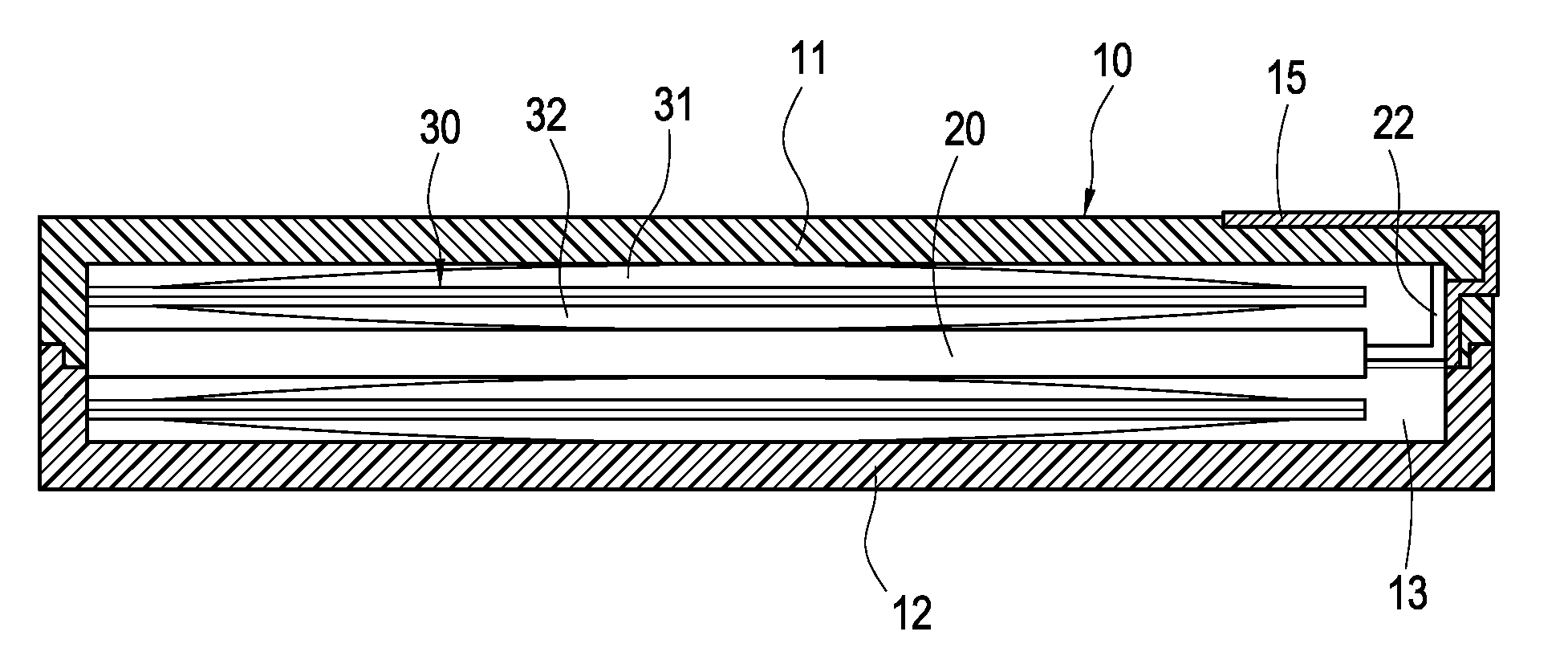
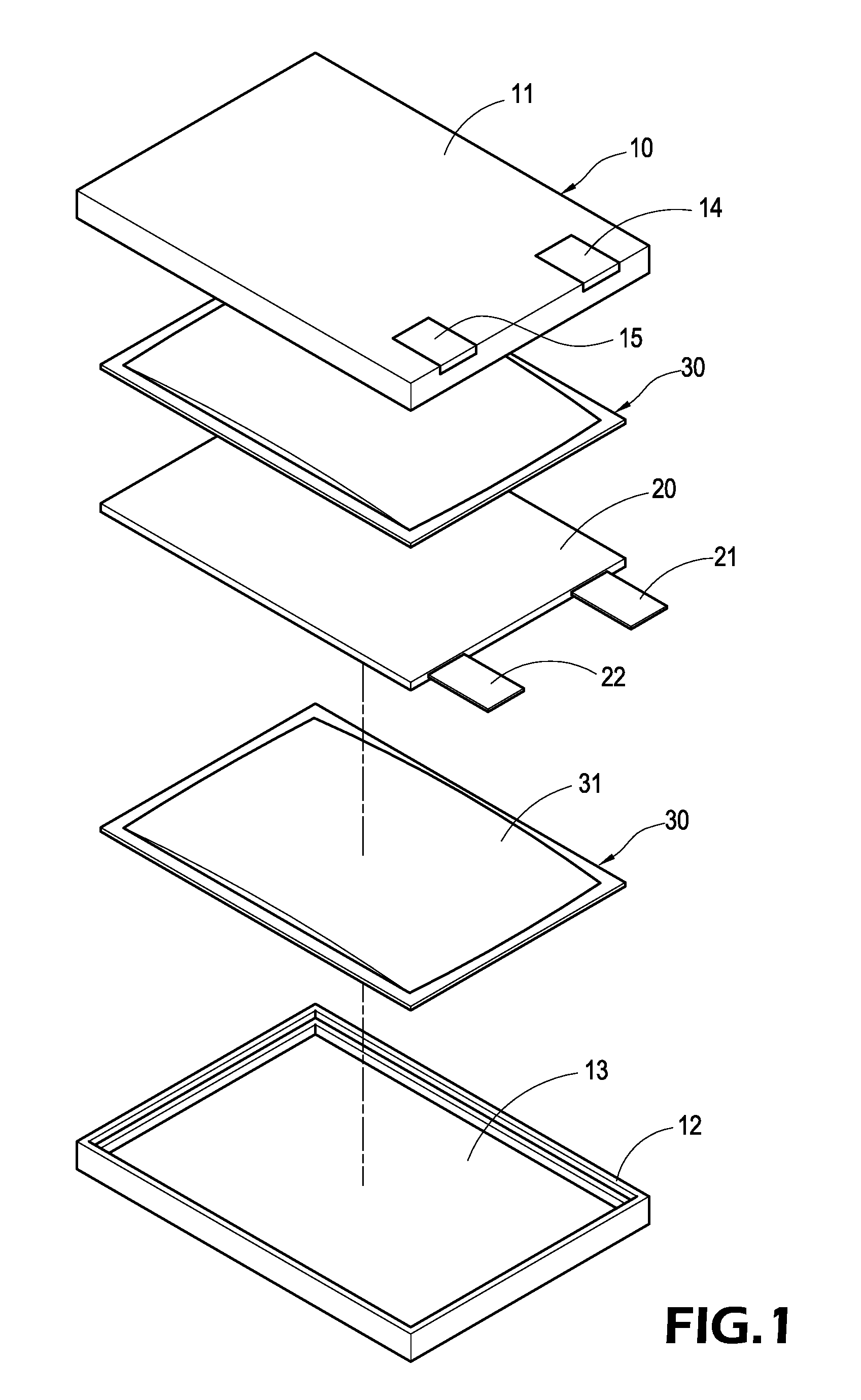
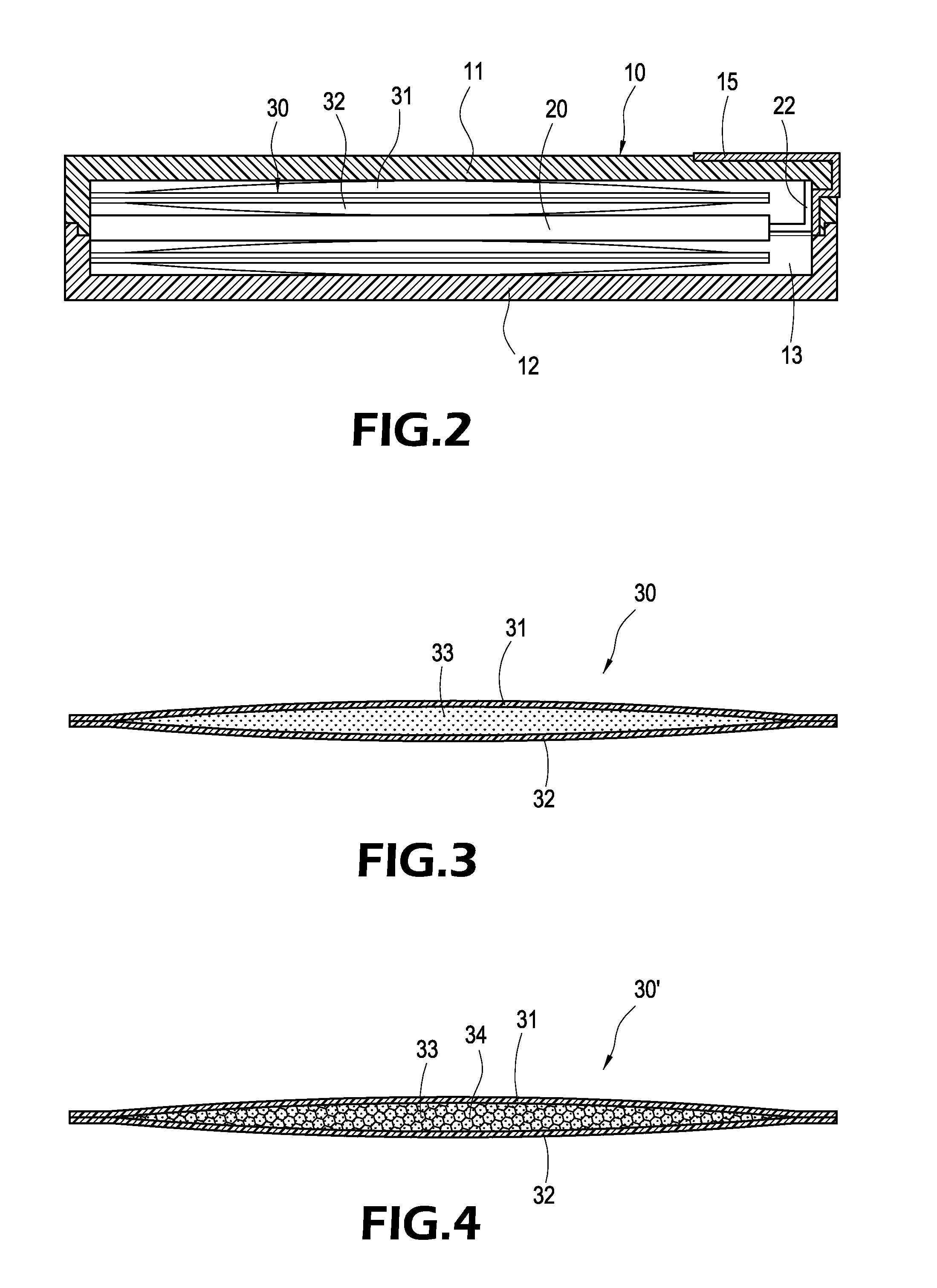
[0019]Referring to FIGS. 1 to 3 for the exploded view and the cross-sectional view of a battery apparatus of the present invention and the cross-sectional view of a heat absorbing body according to a first preferred embodiment of the present invention respectively, the invention provides a battery apparatus with a heat absorbing body, and the preferred embodiment comprises a casing 10, a cell 20 and two heat absorbing bodies 30.

[0020]The casing 10 includes an upper casing panel 11 and a lower casing panel 12 connected to the bottom of the upper casing panel 11, each casing panel 11, 12 could be made of a plastic material, a hollow containing sp...


PUM

PropertyMeasurementUnit
temperatureaaaaaaaaaa
heataaaaaaaaaa

Abstract

A battery apparatus with a heat absorbing body includes a casing, a cell and a heat absorbing body. The casing includes a containing space, an anode and a cathode disposed at the exterior of the casing, and a cell and a heat absorbing body installed in the containing space. The cell includes an anode handle and a cathode handle connected to the anode and cathode respectively. The heat absorbing body is attached onto a surface of the cell and includes an upper soft film and a lower soft film sealed with the upper soft film, and a phase change material is filled between the upper and lower soft films, such that the phase change material can absorb or release large amounts of heat in a phase change process to maintain the cell operated at a lower and more stable operating temperature and extend the life of the battery apparatus.

Description

BACKGROUND OF THE INVENTION[0001]1. Field of the Invention[0002]The present invention relates to a battery apparatus with a heat absorbing body, and more particularly to a battery apparatus that installs and attaches a heat absorbing body between battery cells.[0003]2. Description of Prior Art[0004]As the development of science and technology advances, a plurality of cells are connected in series or in parallel to form a battery apparatus for supplying power for various different appliances. Since the battery apparatus has a low pollution that can comply with the environmental protection requirements and provide a high power current output, the battery apparatuses are used extensively in many electric appliances and equipments including electric tools, electric motorcycles and electric cars. However, such electric appliances and equipments require a power recharge function. Since the output of the electric power is in form of a short-duration high current, each cell results in a hig...

Claims


Application Information

Patent Timeline
Patent Type & Authority Applications(United States)
IPC IPC(8): H01M10/50H01M2/08H01M50/211H01M50/55H01M50/553
CPCH01M2/1061H01M2/20H01M2/30H01M6/46H01M10/5089H01M10/5053H01M10/5055H01M10/5079H01M10/5004H01M10/6569H01M10/6555H01M10/6554H01M10/613H01M10/659Y02E60/10H01M50/55H01M50/553H01M50/211
Inventor CHERNG, JING-YIHLAI, TE-CHUANCHANG, YEN-LING
Owner AMITA TECH
Why Eureka
Try Eureka