Acoustically-powered wireless defibrillator

a wireless defibrillator and wireless technology, applied in the field of implantable devices, to achieve the effects of increasing transmission time, increasing acoustic amplitude, and increasing energy

Active Publication Date: 2007-12-20
EBR SYST
View PDF14 Cites 30 Cited by
  • Summary
  • Abstract
  • Description
  • Claims
  • Application Information

AI Technical Summary

Benefits of technology

[0012]In a manner similar to the wireless acoustic pacemaker, the wireless acoustic implantable defibrillator described herein also comprises a subcutaneously implanted controller-transmitter operating in conjunction with a receiver-defibrillator (similar to the receiver-stimulator of the wireless acoustic pacemaker) device located within the chambers of the heart. These components of the defibrillator and their pacemaker counterparts have significant differences, because of the differences in energy requirements and applied electrical waveform of a defibrillator versus a pacemaker, and in the frequency of application of this energy. In a defibrillator, the acoustic transmitter must transmit a much larger amount of energy to effect defibrillation, either through increased acoustic amplitude, increased transmission time, or both. However, a defibrillator device may only need to apply this energy a small number of times over the lifetime of the device. Both of these requirements are in contrast to a bradycardia pacemaker, which must supply a very small amount of energy, typically at the rate of 60-80 times per minute, continuously for a period of many years. Even anti-tachycardia pacing, which is typically delivered at a rate of 150-200 beats per minute, is only performed typically a few times per year.

Problems solved by technology

However, a defibrillator device may only need to apply this energy a small number of times over the lifetime of the device.

Method used


Image

  • Acoustically-powered wireless defibrillator
  • Acoustically-powered wireless defibrillator
  • Acoustically-powered wireless defibrillator

Examples


Embodiment Construction

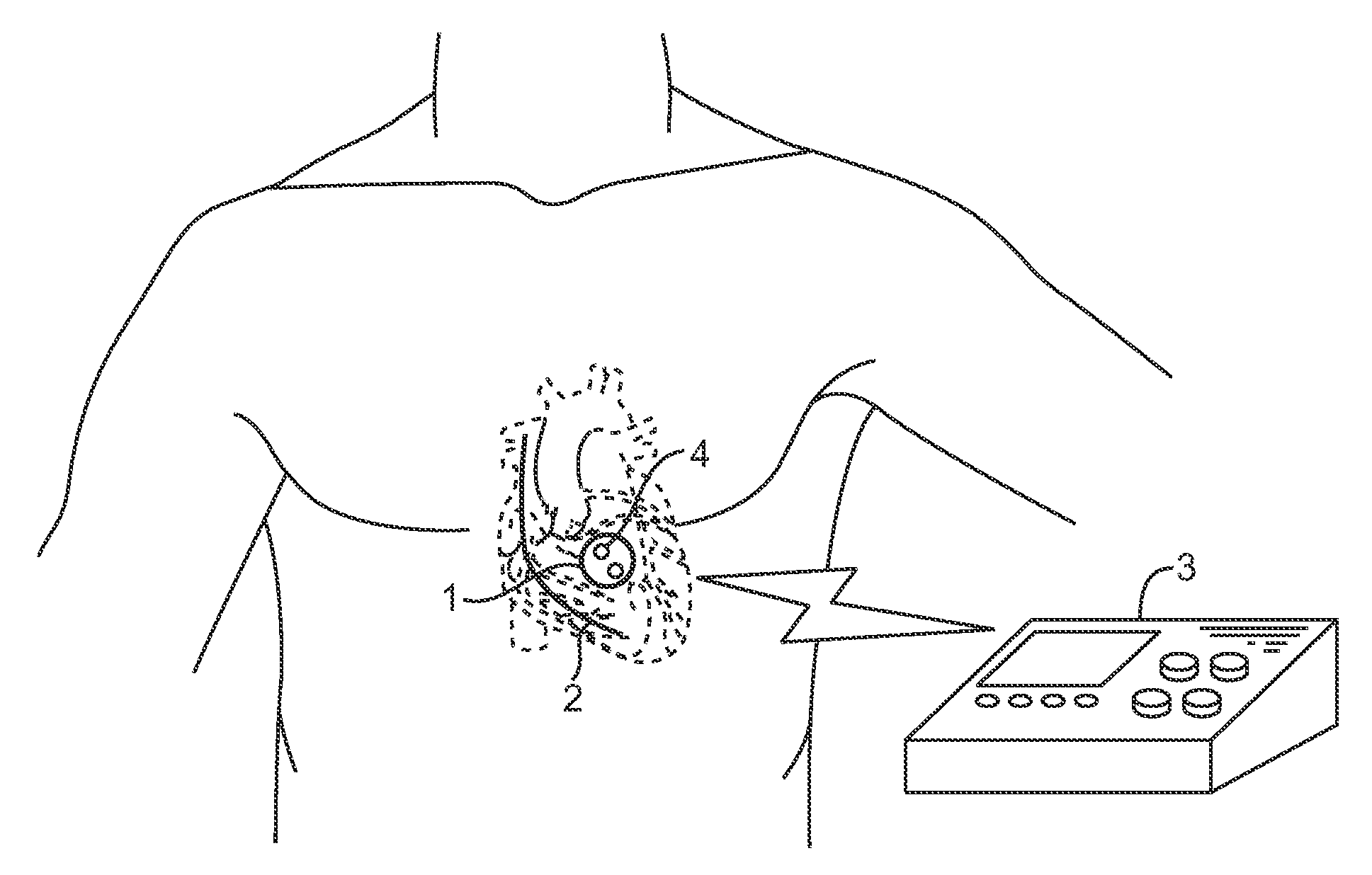
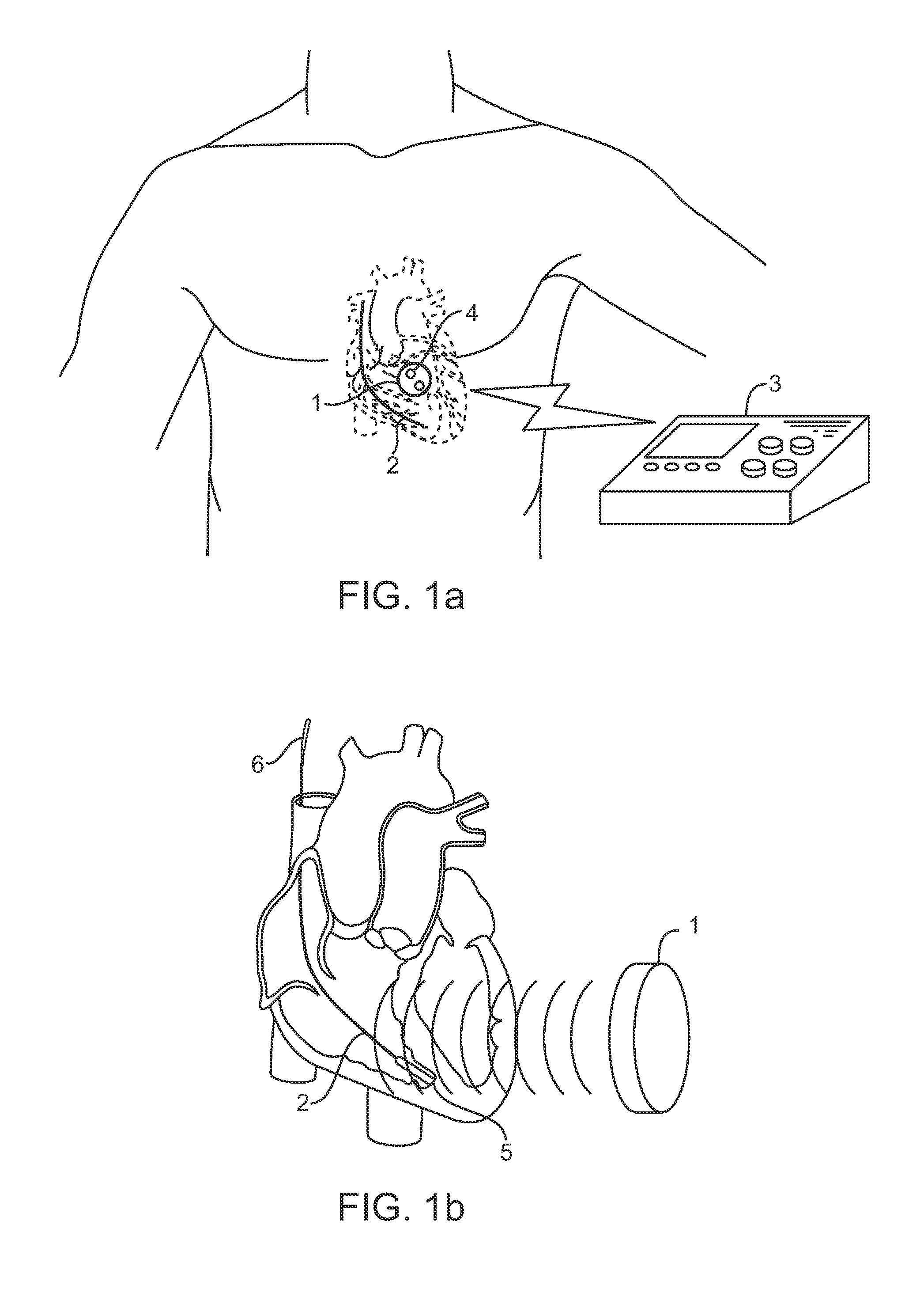
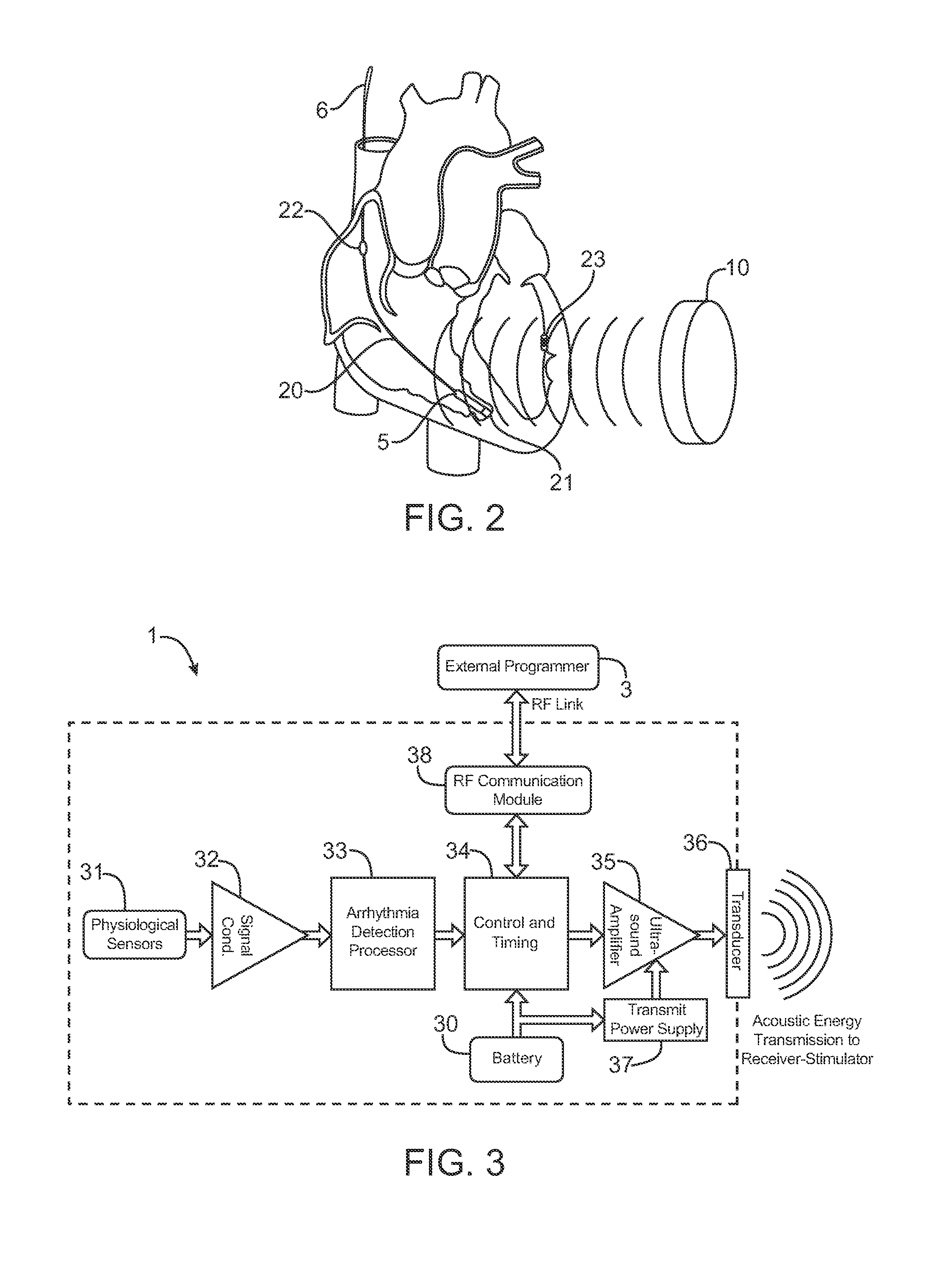
[0022]The invention described here comprises a subcutaneously implanted controller-transmitter device that transmits acoustic energy to an implanted receiver-defibrillator device, which converts the acoustic energy to electrical energy, stores and accumulates a sufficient quantity of energy, and then discharges such energy in a preferred waveform between at least two electrodes disposed on or about the receiver-defibrillator device in order to terminate an undesirable cardiac rhythm. The acoustic energy can be delivered as single or multiple bursts, preferably using ultrasound. The ultrasound frequency may range from 20 kHz to 10 MHz, preferably 100 kHz to 1 MHz, and more preferably from 250 to 500 kHz. The ultrasound transmit burst length (or accumulated burst length in the event of multiple bursts) will be less than 10 seconds, preferably less than 5 seconds, and more preferably less than 2 seconds.

[0023]The controller-transmitter device comprises one or more ultrasound transducer...


PUM


Abstract

An acoustic transmitter produces a pulsed ultrasound waveform which is transmitted through body tissues to an implanted receiver-stimulator device. The waveform has an acoustic amplitude, pulse width, and pulse repetition period, which corresponds to a pacing pulse electrical amplitude, pacing pulse width, and pacing cycle length, respectively. The receiver-stimulator device intercepts at least a portion of the transmitted acoustic energy and coverts that acoustic energy into electrical energy using piezoelectric or other devices. This electrical energy is applied to circuitry, which produces a desired stimulating pulse waveform, which is then applied to tissue-contacting electrodes.

Description

CROSS-REFERENCES TO RELATED APPLICATIONS[0001]The present application claims the benefit of provisional U.S. Application No. 60 / 805,312 (Attorney Docket No. 021834-001400US), filed Jun. 20, 2006, the full disclosure of which is incorporated herein by reference.BACKGROUND OF THE INVENTION[0002]1. Field of the Invention.[0003]This invention relates to implantable devices used to defibrillate and pace the heart and more specifically to systems and methods for providing such defibrillation and pacing that transmit energy acoustically from an implanted transmitter to an implanted receiver without the use of conventional lead / electrode systems.[0004]Currently available implantable cardioverter-defibrillator (ICD) devices apply an electrical defibrillation shock to the heart through a lead wire having an electrode, such lead wire and electrode typically being placed within the right ventricle of the heart, and with the shock typically being delivered between this first electrode and the po...

Claims


Application Information

Patent Timeline
Patent Type & Authority Applications(United States)
IPC IPC(8): A61N1/39
CPCA61N1/3787A61N1/3975A61N1/3968A61N1/3962A61N1/39622
Inventor COWAN, MARK W.BRISKEN, AXEL F.
Owner EBR SYST
Why Eureka
Try Eureka