
Interior connecting interbody cage insertional tools, methods and devices

a technology of interbody cages and insertion tools, applied in the field of interbody spinal systems, can solve the problems of increasing the time and complication of surgery, affecting the accuracy of insertion, and the limited surface area of the interbody device, so as to achieve more accurate placement of the interbody cage, less likely to violate, and safer

Inactive Publication Date: 2007-12-20
WARSAW ORTHOPEDIC INC
View PDF40 Cites 138 Cited by
  • Summary
  • Abstract
  • Description
  • Claims
  • Application Information

AI Technical Summary

Benefits of technology

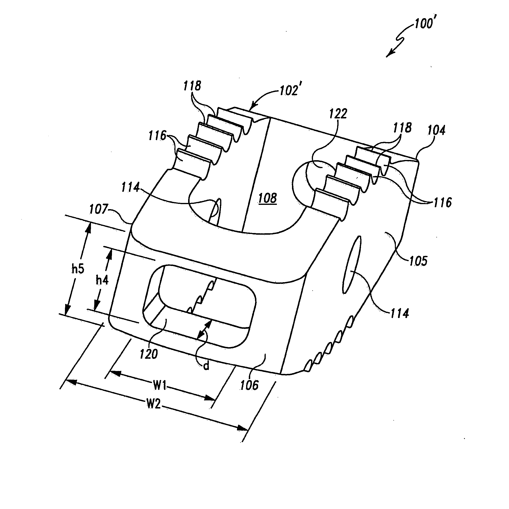
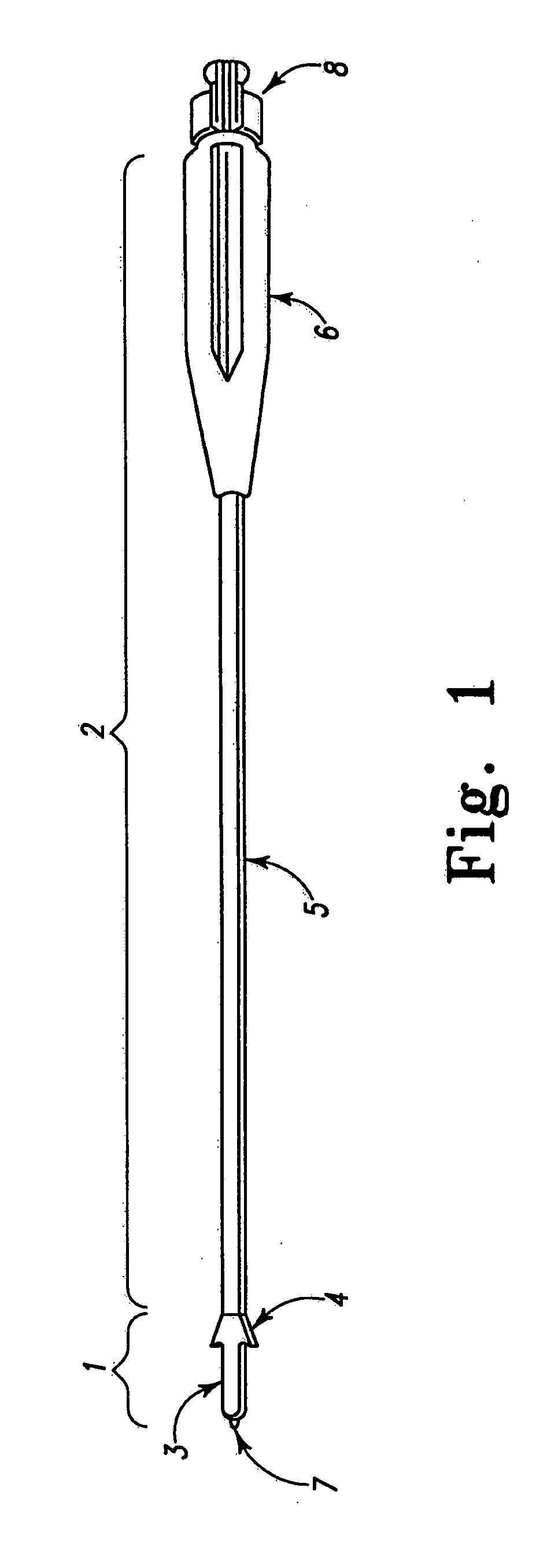
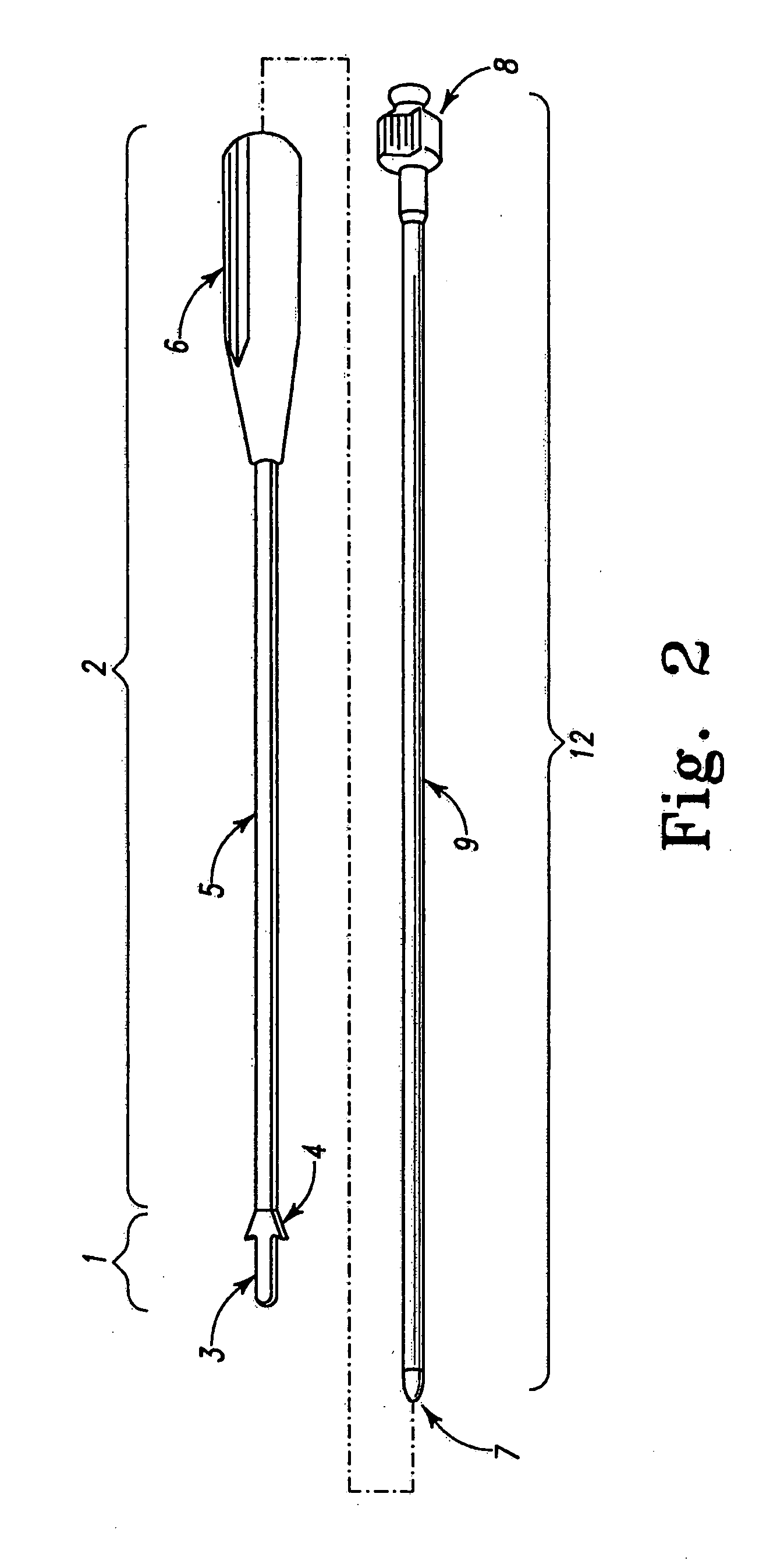
The present invention provides tools, methods, and devices for inserting interbody cages into the spine. These tools help improve the accuracy and safety of cage placement while maintaining the structural integrity of the cage. The tools have a coupling member that engages the trailing end of the cage and an inner shaft that extends through the cage to engage the leading end. The coupling member has a through-opening that allows for maximum surface area contact with the cage, reducing stress on the cage during insertion. The cage body has a rounded nose with a hollow interior and a through-opening in communication with the hollow interior. These features help improve the placement of interbody cages and facilitate spine fusion.

Problems solved by technology

One potential problem with conventional interbody insertional tools is that the most commonly employed means to connect the inserter to its device is relatively weak and may break if substantial forces are applied during the insertion process.
This weak connection can result in suboptimal placement in the interbody space or even a loss of control of the interbody device during placement, increasing the time and complication of the surgery.
Another potential problem with conventional interbody insertional tools is that insertional forces are applied limited surfaces of the interbody device.
This could lead to deformation, fatigue and other forces being exerted on the device.
Another potential problem with conventional interbody insertional tools is that the vise-like inserters reduce visibility because of their bulk.
While these devices may be suitable for the particular purpose to which they address, they are not as suitable for making placement of interbody cages more accurate, safer and less likely to violate the structural integrity of the interbody cage.

Method used


Image

  • Interior connecting interbody cage insertional tools, methods and devices
  • Interior connecting interbody cage insertional tools, methods and devices
  • Interior connecting interbody cage insertional tools, methods and devices

Examples


Embodiment Construction

[0027] For the purpose of promoting an understanding of the principles of the invention, reference will now be made to the embodiments illustrated in the drawings and specific language will be used to describe the same. It will nevertheless be understood that no limitation of the scope of the invention is thereby intended. Any alterations and further modifications in the described embodiments, and any further applications of the principles of the invention as described herein are contemplated as would normally occur to one skilled in the art to which the invention relates.

[0028] Insertional tools, methods and devices for interbody stabilization are provided that facilitate control and positioning of the leading end of the cage to be inserted. Placement of interbody cages can be more accurate, efficient, and less likely to violate the structural integrity of the interbody cage. Insertional tools and cages are configured so that the inserter tips fit into and positively lock with the...


PUM


Abstract

Interior connecting interbody cage insertional tools, methods and devices are provided wherein the same can be utilized for making placement of interbody cages more accurate, safer and less likely to violate the structural integrity of the interbody cage while providing support to a leading end of the cage as the leading end re-capitulates or distracts the disc space as the cage is inserted.

Description

CROSS-REFERENCE TO RELATED APPLICATIONS [0001] This application is a continuation of PCT Application No. PCT / US2005 / 037649 filed on Oct. 10, 2005, which claims priority to and the benefit of the filing date of Provisional Application Ser. No. 60 / 617,280 filed on Oct. 8, 2004, each of which is incorporated herein by reference in its entirety.BACKGROUND [0002] 1. Field of the Invention [0003] The present invention relates generally to interbody spinal systems and more specifically it relates to interior connecting interbody cage insertional tools, methods and devices for making placement of interbody cages more accurate, safer and less likely to violate the structural integrity of the interbody cage. [0004] 2. Description of the Related Art [0005] It can be appreciated that interbody insertional tools have been in use for years. Typically, interbody insertional tools are comprised of insertion tools used to introduce and properly position various types of devices into the interbody sp...

Claims


Application Information

Patent Timeline
Patent Type & Authority Applications(United States)
IPC IPC(8): A61F2/44
CPCA61F2/28A61F2310/00359A61F2/4611A61F2002/30057A61F2002/30112A61F2002/30235A61F2002/30266A61F2002/30331A61F2002/30405A61F2002/30601A61F2002/30772A61F2002/30904A61F2002/4475A61F2002/4627A61F2002/4629A61F2220/0025A61F2220/0033A61F2230/0004A61F2230/0069A61F2230/0082A61F2/4455A61F2002/30593
Inventor SALERNI, ANTHONY A.PETERMAN, MARC M.MOORE, JEFFREY D.
Owner WARSAW ORTHOPEDIC INC
Learn More