Dryer, Drying Method and Drying Paint

Active Publication Date: 2007-12-27
ETC COLDRY PTY LTD
View PDF15 Cites 14 Cited by
  • Summary
  • Abstract
  • Description
  • Claims
  • Application Information

AI Technical Summary

Problems solved by technology

However, as a result of high moisture content of such materials they are of relatively low energy value and have relatively high mass to energy content ratio.
This means that it is often not economically viable to transport such materials far from where they are deposited and that unless deposits are located close to the surface they may not constitute a viable energy source.
Furthermore, the high moisture content of such materials means that their combustion is not clean and gives rise to more unwanted combustion by-products than combustion of higher rank carbonaceous materials.
Furthermore, the large tonnages of the pellets required to be dried, are typically stored in open air heaps and adequate air circulation to all pellets during drying can be problematic.

Method used


Image

  • Dryer, Drying Method and Drying Paint
  • Dryer, Drying Method and Drying Paint
  • Dryer, Drying Method and Drying Paint

Examples


second embodiment

[0074]FIG. 3 illustrates a dryer 110 of the invention which comprises a series of adjacent dryer unit cells 160, which are separated at substantially regular intervals by internal membrane walls 162. Each unit cell 160 includes two opposed louvred walls 120a and 120b having the same basic construction as shown in FIGS. 4 and 5. These walls have converging lower extensions 128a and 128b, which are tapered towards an outlet 118. Each membrane wall 162 extends the entire height and width of the dryer such as to effectively isolate the interior of each cell 160 from each other. Adjacent unit cells 160 share a common membrane wall 162.

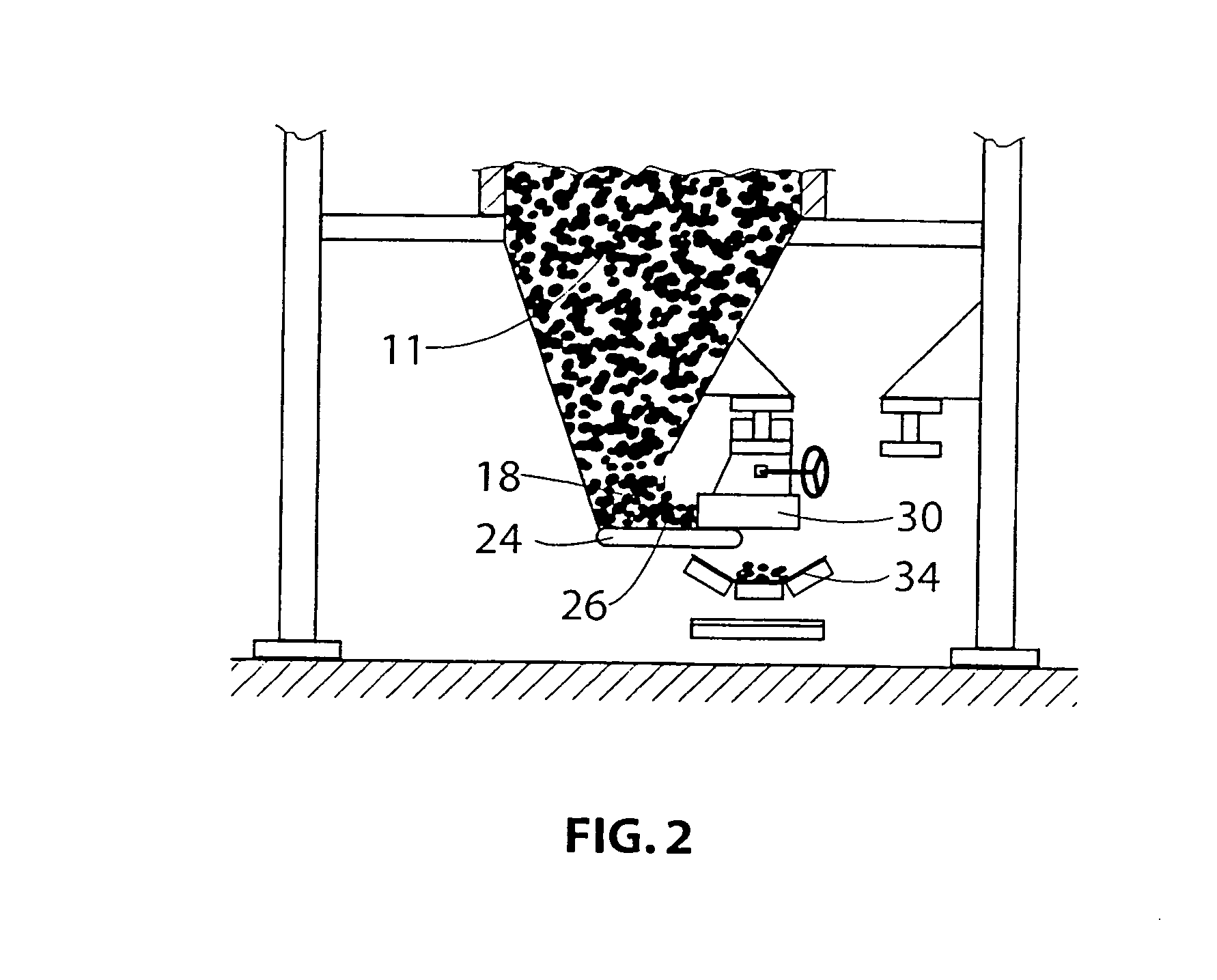
[0075]FIGS. 6a and 6b together illustrate a drying plant 200 incorporating the dryer 210 of the invention. The plant 200 also includes a compactor, indicated generally by the reference numeral 270, a conditioning bed, indicated generally at 271, a conveyor indicated generally at 272, discharger 273 and pellet remover 274.

[0076] Referring to FIG. 6a, a coal...

third embodiment

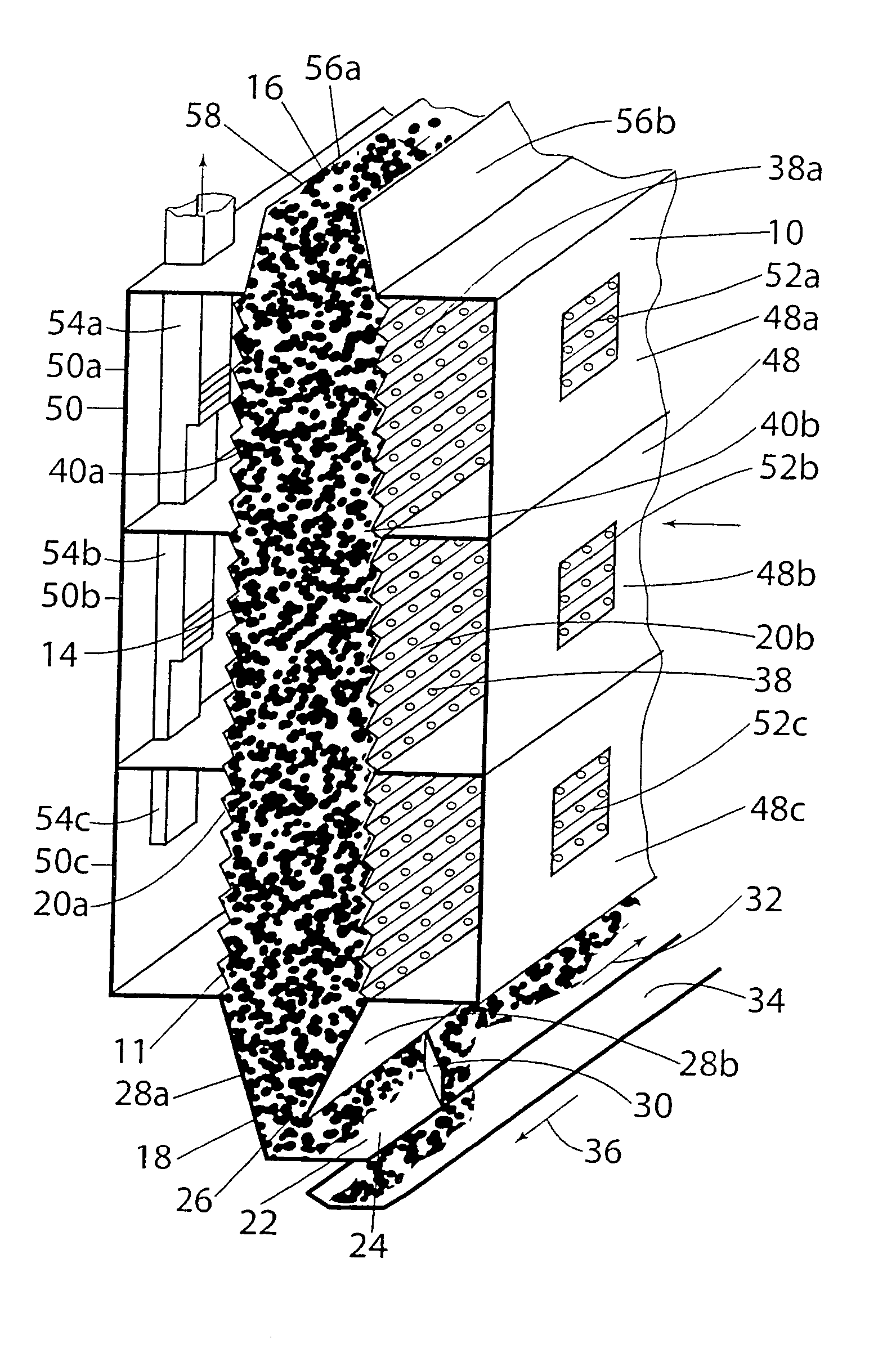
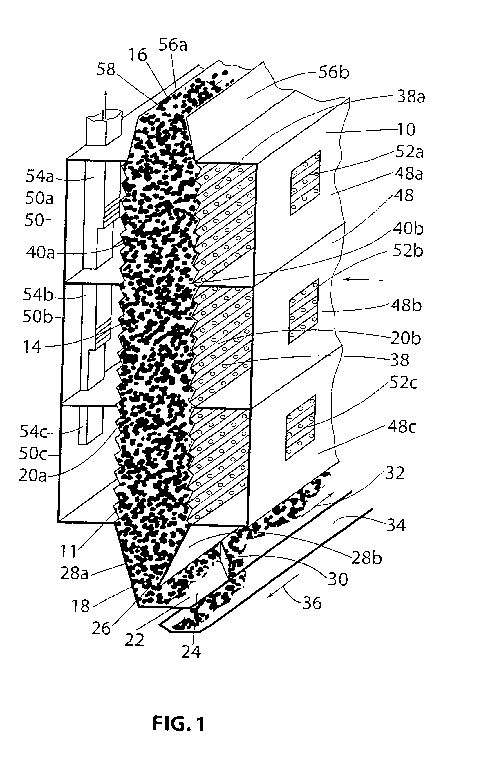
[0079] the dryer of the invention is shown generally at 310 in FIG. 7, in which like reference numerals relate to like parts. Discussion of FIG. 7 will focus on those features that differ from the embodiment shown in FIG. 1. The dryer 310 includes air plenums 348 and 350 provided on the surfaces of the permeable walls 320b and 320a, respectively. The air plenums 348 and 350 are divided into air plenum zones 348a, b, c and d and 350a, b, c and d, respectively. The drying gas, comprising preheated air, is sucked into plenum zone 350d and through the elongate container 314 into the opposing plenum zone 348d, by virtue of an air circulation means, comprising a fan 351 located in the opposing plenum zone 348d. An opening 353 between adjacent plenum zones 348d and 348c allows the air stream to be sucked into plenum zone 348c under action of a second fan 355 located in plenum zone 350c. The air stream therefore travels from plenum zone 348c, through the container 314 into the opposing plen...


PUM


Abstract

The invention provides a dryer for drying particulate material, comprising at least one substantially vertical elongate container having an upper inlet (56a, 56b) for receiving a charge of moisture containing particulate material; a lower outlet (22) for discharging dried particulate material, whereby said particulate material travels under the influence of gravity from said inlet to said outlet; at least one substantially vertical gas permeable wall (20a, 20b) through which a drying gas can pass to contact said particulate material; said dryer also comprising at least one plenum (48, 50) on an exterior surface of said at least one gas permeable wall, covering ingress (38a) and egress openings within said at least one gas permeable wall.

Description

FIELD OF THE INVENTION [0001] The present invention relates to a dryer, a drying method and a drying plant, each for use in drying particulate material. The invention particularly relates to a dryer, drying method and drying plant for use in drying pellets containing low rank carbonaceous material, such as brown coal, peat, certain soft lignites, anaerobically decomposed plant matter, or any combination thereof. BACKGROUND OF THE INVENTION [0002] Low rank carbonaceous materials, such as brown coal, are a basic energy source in many regions of the world. The use of such materials for the provision of energy is often convenient due to their abundant supply and location in the vicinity of energy requirements. However, as a result of high moisture content of such materials they are of relatively low energy value and have relatively high mass to energy content ratio. This means that it is often not economically viable to transport such materials far from where they are deposited and that...

Claims


Application Information

Patent Timeline
IPC IPC(8): F26B17/12C10F5/00F26B21/08
CPCC10F5/00F23K1/04F23K2201/20F26B25/12F26B17/126F26B21/08F26B17/122B29B9/16
Inventor WILSON, DAVID
Owner ETC COLDRY PTY LTD
Why Eureka
Try Eureka