Oscillatory Drive

Active Publication Date: 2007-12-27
C & E FEIN
View PDF5 Cites 76 Cited by
  • Summary
  • Abstract
  • Description
  • Claims
  • Application Information

AI Technical Summary

Benefits of technology

[0012] In view of this, it is a first object of the present invention to disclose an improved oscillator

Problems solved by technology

However, when used in continuous operation, oscillatory drives have also shown

Method used


Image

  • Oscillatory Drive
  • Oscillatory Drive
  • Oscillatory Drive

Examples


Embodiment Construction

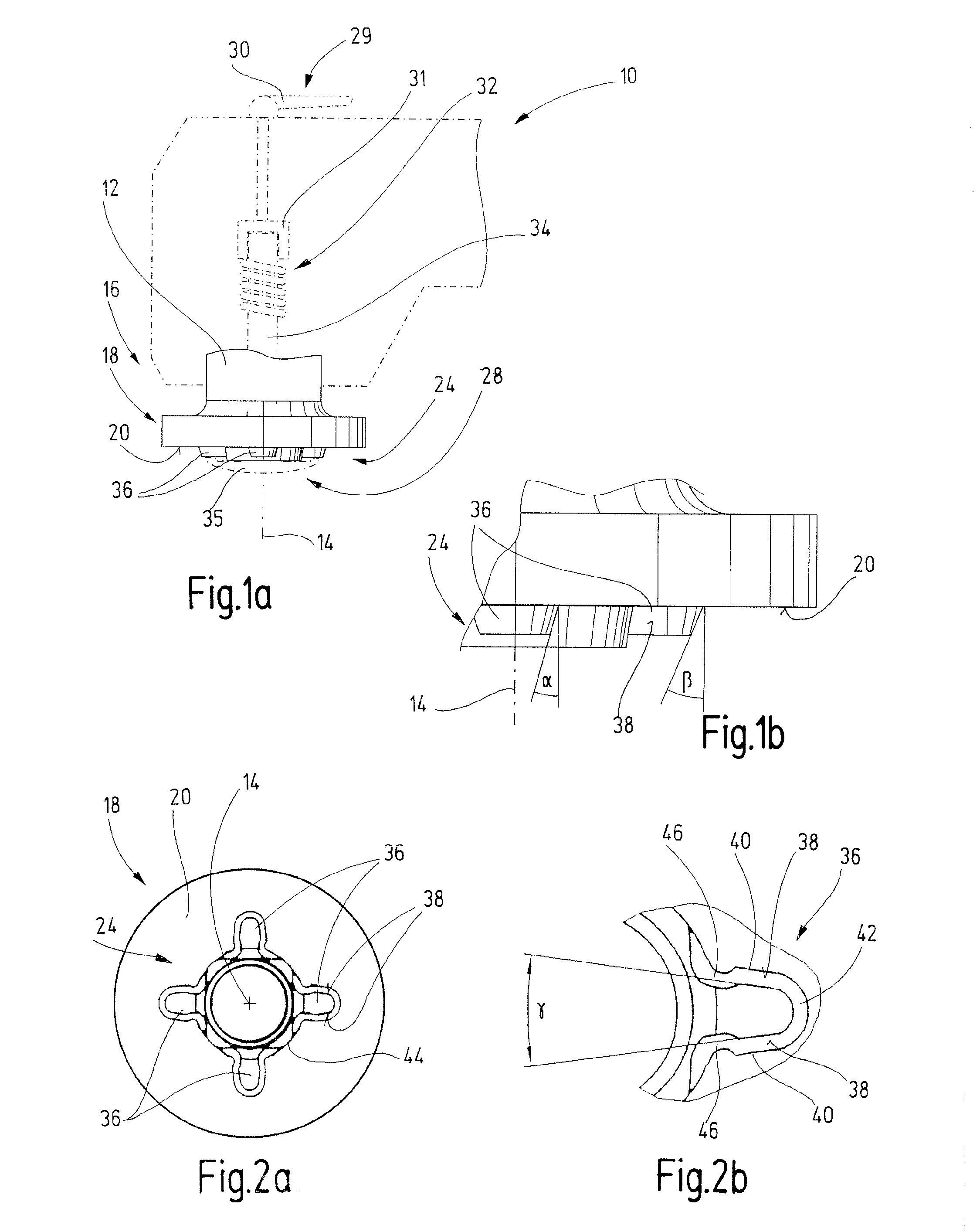
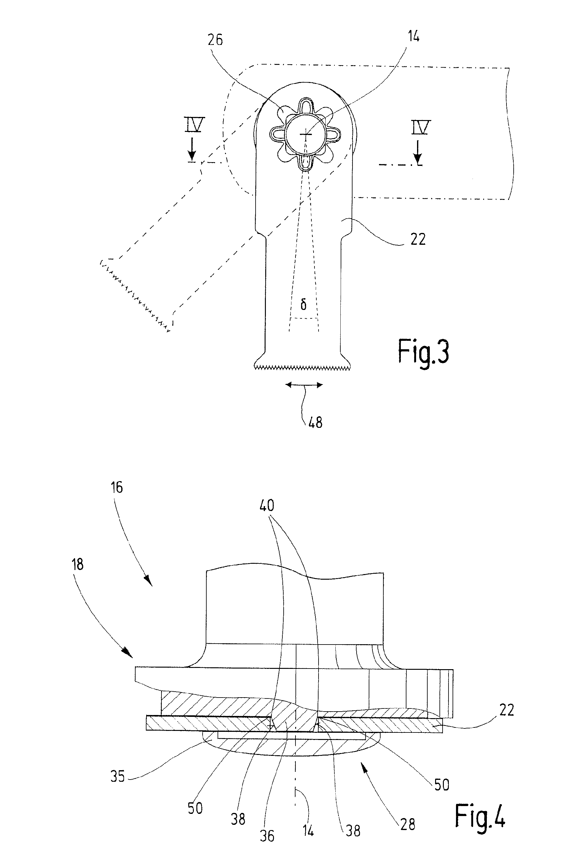
[0056]FIG. 1a shows an oscillatory drive 10 with an output shaft 12, that can be driven to oscillate rotatingly about its longitudinal axis 14, and with a free end 16. The free end 16 carries a holding fixture 18 with a contact surface 20 intended to receive a tool 22 (FIG. 3). An enlarged detail of the holding fixture 18 is illustrated in FIG. 1b.

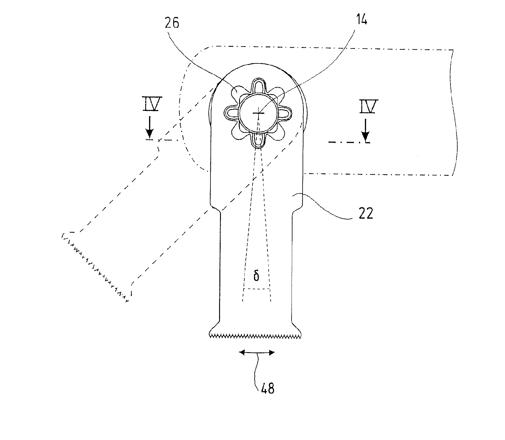
[0057] A mounting section 24 arranged on the holding fixture 18 projects outwardly from the contact surface 20 in the direction of the longitudinal axis 14 and is adapted for form-locking connection to a mounting opening 26 (FIG. 3) of a tool 22 attached to the contact surface 20.

[0058] The oscillatory drive 10 further comprises a quick-change clamping device 29 with a clamping lever 30 by means of which a tension element 31 received in the output shaft 12 can be displaced axially between a working position and an inoperative position. The tension element 31 may carry a securement 28, for example in the form of a screw, that passes throu...


PUM


Abstract

The invention relates to an oscillatory drive having an output shaft that can be driven to perform a rotationally oscillating movement about its longitudinal axis and that comprises a free end, a holding fixture at the free end of the output shaft comprising a contact surface for attachment of a tool, a mounting section on the holding fixture, raised relative to the contact surface, that projects to the outside in the direction of the longitudinal axis and that is designed for form-locking connection with a mounting opening of a tool placed in contact with the contact surface, and having a securement for fixing the tool with its mounting opening on the holding fixture, the securement permitting the tool to yield in axial direction under the action of a torque, against a pre-stress, and the mounting section permitting the tool to rotate by a certain angle of rotation when the tool gives way axially.

Description

CROSS-REFERENCE TO RELATED APPLICATIONS [0001] The present application claims priority of German patent application 10 2006 021 969.4 filed on May 4, 2006, the content of which is incorporated herein by reference. FIELD OF THE INVENTION [0002] The present invention relates to an oscillatory drive having [0003] an output shaft that can be driven to perform a rotationally oscillating movement about its longitudinal axis and that comprises a free end, [0004] a holding fixture at the free end of the output shaft comprising a contact surface for attachment of a tool, [0005] a mounting section on the holding fixture, raised relative to the contact surface, that projects to the outside in the direction of the longitudinal axis and that is designed for form-locking connection with a mounting opening of a tool placed in contact with the contact surface, and [0006] a securement for fixing the tool with its mounting opening on the holding fixture. BACKGROUND OF THE INVENTION [0007] An oscillat...

Claims


Application Information

Patent Timeline
IPC IPC(8): F16G11/12G05G1/14G05G1/30
CPCB24B23/04B24B45/00Y10T279/16Y10T279/15Y10T74/2164Y10T403/291
Inventor ZIEGLER, ROLFFRUEH, UWEHECHT, ADOLF
Owner C & E FEIN
Why Eureka
Try Eureka