

Torsional vibration damper
- Summary
- Abstract
- Description
- Claims
- Application Information
AI Technical Summary
Benefits of technology
Problems solved by technology
Method used
Image

Examples
Embodiment Construction
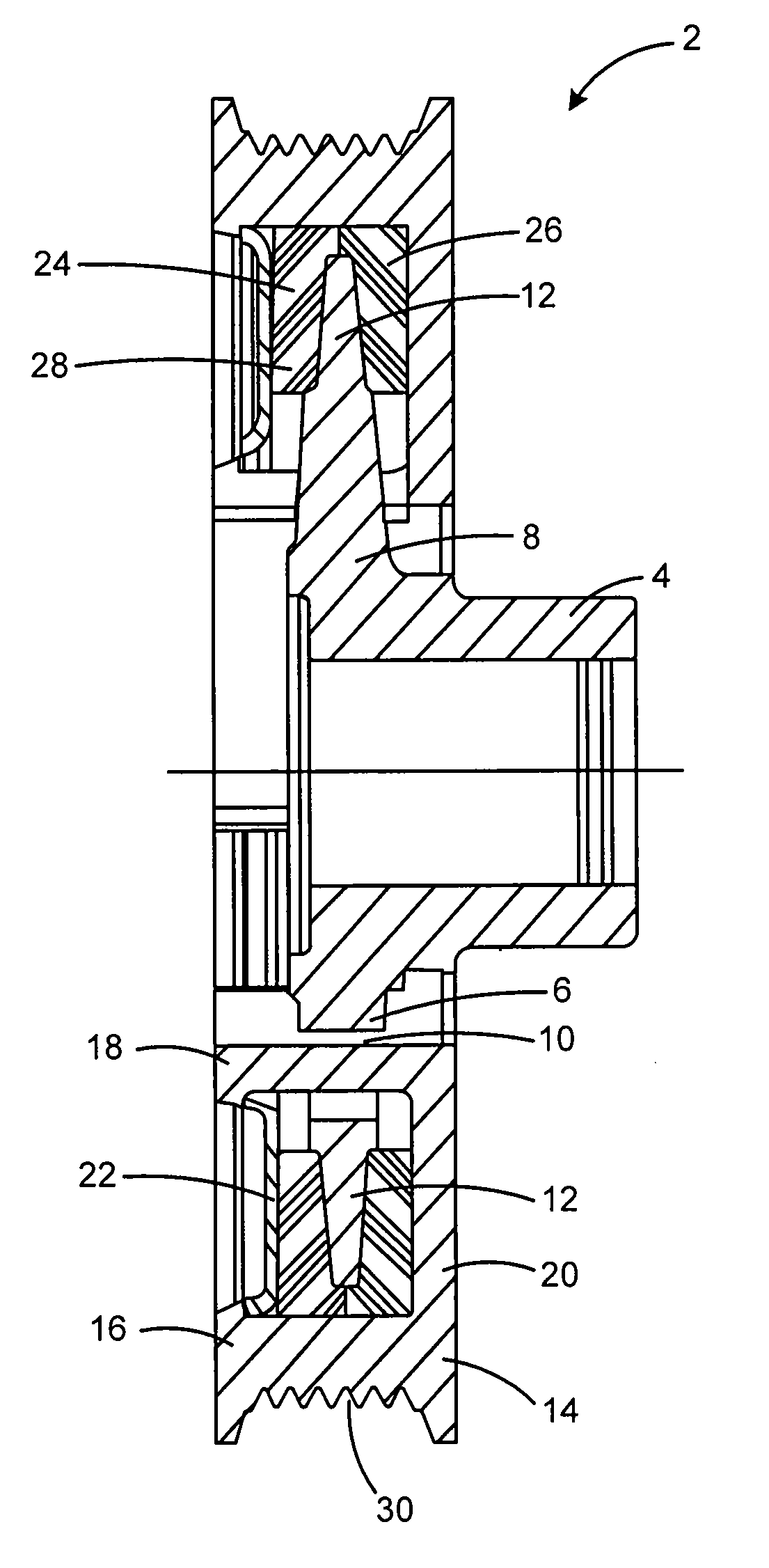
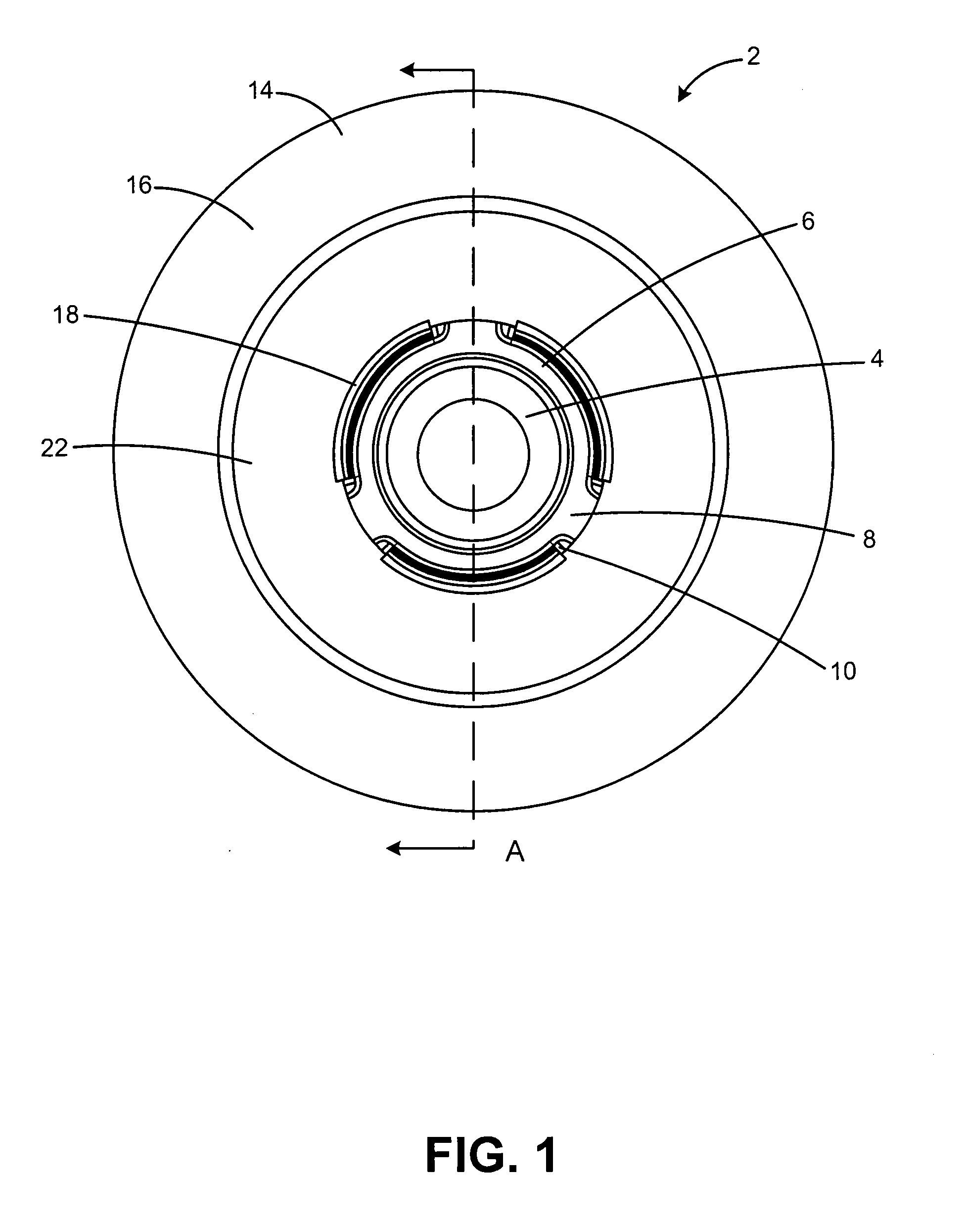
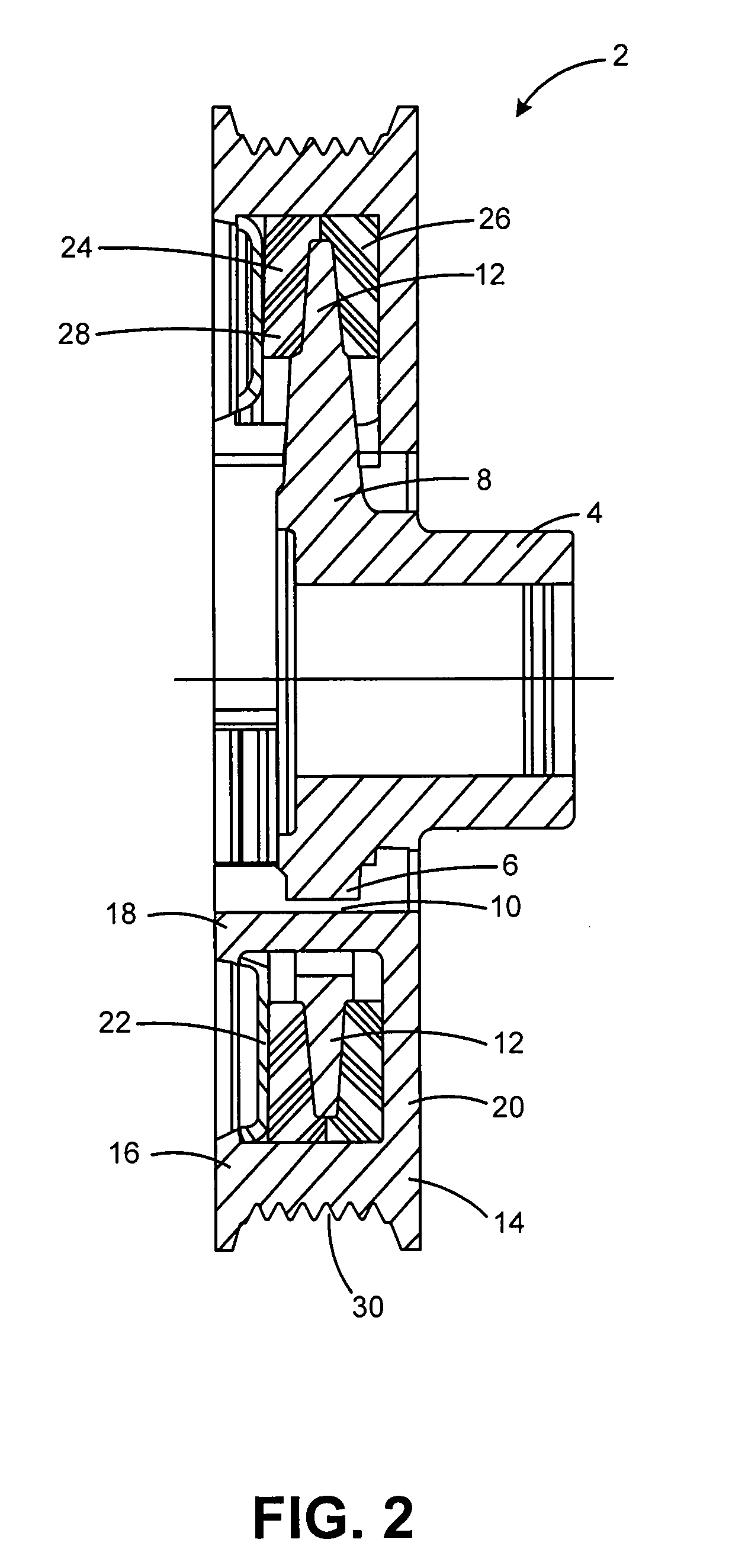
[0016]The following description is of certain exemplary embodiments of the present invention only, and is not intended to limit the scope, applicability or configuration of the invention. Rather, the following description is intended to provide a convenient illustration for implementing various embodiments of the invention. As will become apparent, various changes may be made in the function and arrangement of the elements described in these embodiments without limiting or diminishing the scope of the invention as set forth herein. It should be appreciated that the description herein may be adapted to be employed with alternatively configured devices having different shapes, components, materials and the like and still fall within the scope of the present invention. Thus, the detailed description herein is presented for purposes of illustration only and not of limitation.
[0017]A torsional vibration damper according to various embodiments of the present invention includes an annular ...
PUM
 Abstract
Description
Claims
Application Information