
Transport discharge material flow regulation device and method

a technology of flow regulation device and discharge material, which is applied in the direction of transportation and packaging, loading/unloading, conveyor parts, etc., can solve the problems of reducing the service life reducing the efficiency of the transport facility, and reducing the horizontal movement of offloaded materials. , the effect of reducing the excavation and downtime of the transport facility

Inactive Publication Date: 2007-12-27
ASHROSS
View PDF10 Cites 8 Cited by
  • Summary
  • Abstract
  • Description
  • Claims
  • Application Information

AI Technical Summary

Benefits of technology

[0010] It has been recognized that it would be advantageous to develop a method and device for rapidly unloading a hopper type bulk material transport that minimizes excavation and downtime of transport facilities during installation. In addition, it has been recognized that it would be advantageous to develop a method and device to rapidly unloading a hopper type bulk material transport that provides for access to facilitate servicing and preventive maintenance. Furthermore, it has been recognized that it would be advantageous to develop a method and device for reducing horizontal movement of offloaded material still in contact with the transport vehicle while permitting horizontal movement of offloaded material below the transport vehicle.
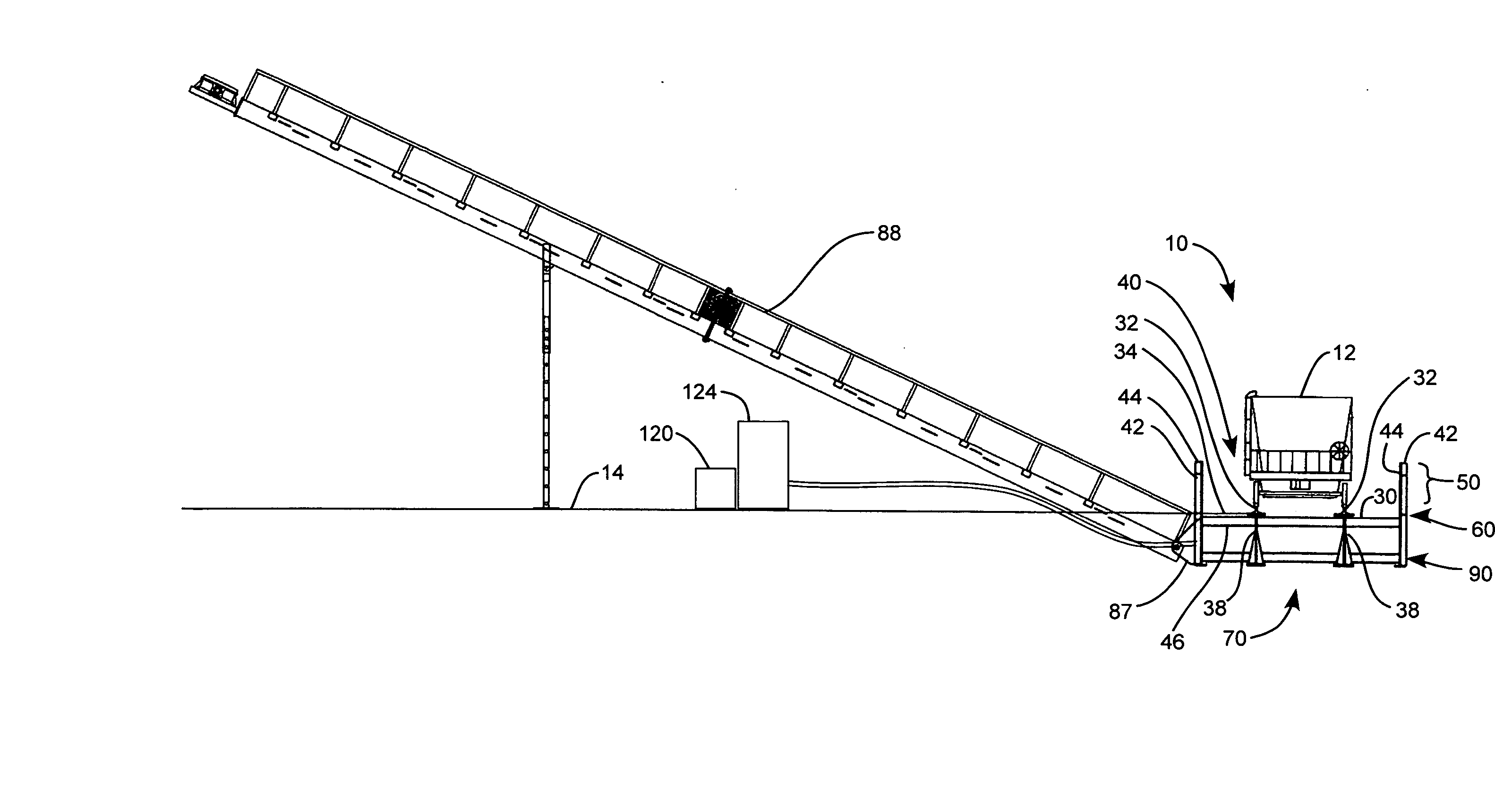
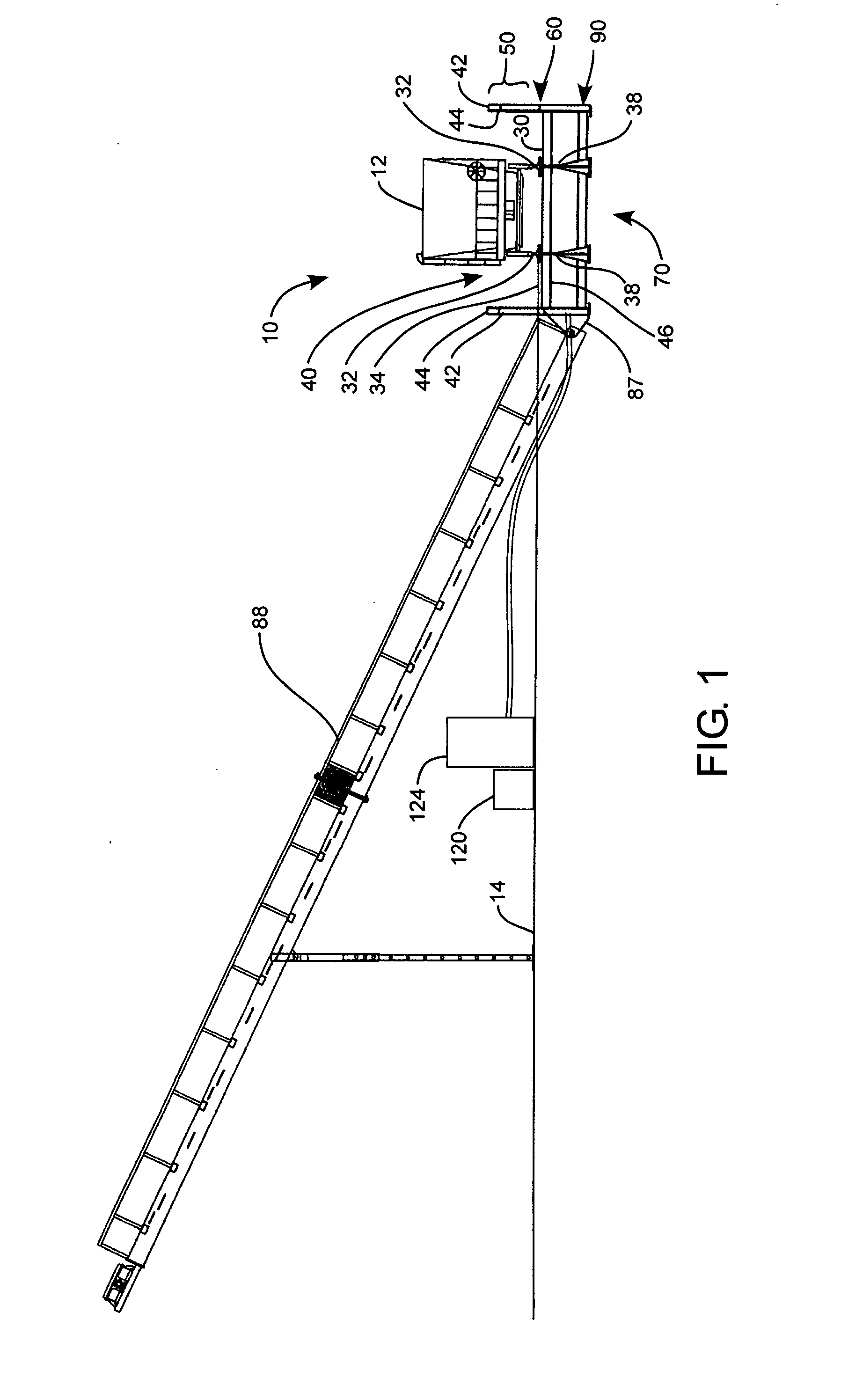
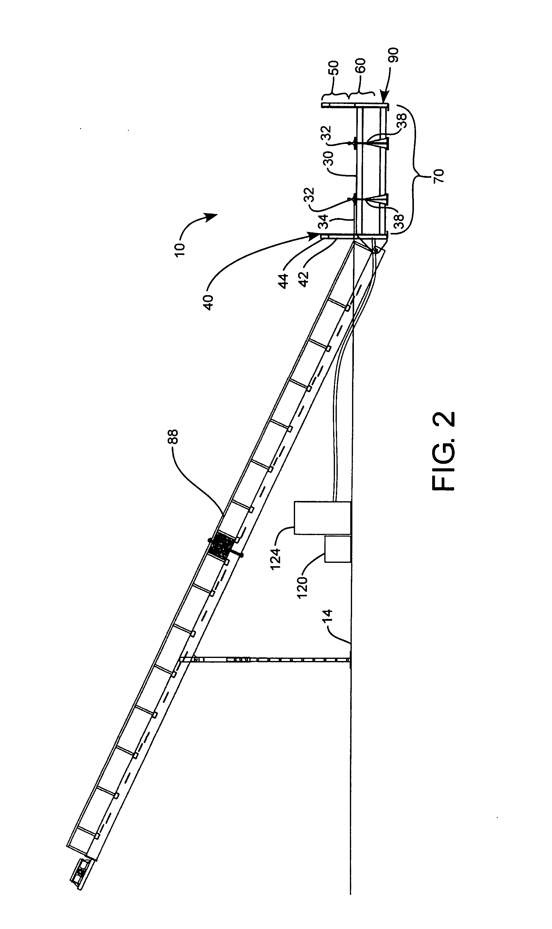
[0011] The invention provides a bulk material unloading station configured to rapidly receive and transfer the contents of a bulk material transport vehicle. The unloading station can include an unloading platform that can be alignable with an existing thoroughfare at an approximate ground level. A frame can disposed about the unloading platform, and can define a material flow control space for controlling the containment and flow rate of material unloaded from the bulk material transport vehicle. The material flow control space can have an upper containment portion that can be disposed above the unloading platform. The upper containment portion can contain an overflow of bulk material as the bulk material is unloaded on the unloading station. The material flow regulation space can also have a lower material flow regulation space disposed below the unloading platform. The material flow regulation space can control the flow rate of bulk material unloading onto the unloading platform and can minimize the transference of horizontal or shear forces from a lower portion of material to an upper portion of material. A conveyor system can be operably associated with the lower material flow regulation space, and can operate to horizontally move a lower portion of the bulk material.

Problems solved by technology

However, while these vehicles can usually dump the material relatively quickly, moving the material away from the dump site is generally a much slower process.
Consequently, dumping or discharging the bulk material from the hopper car is often slowed by the limited ability to move the material away from the hopper as it is discharged.
However, this unloading system requires significant and expensive excavation which results in extensive down time and loss of productivity of the unloading station during installation.
Additionally, ground water contamination, environmental permits, and expense of finding bypass transport facilities during installation are also problems for these systems.
These mobile conveyor systems don't require expensive and lengthy excavation; however, they take longer to offload the bulk material because the conveyor belt can only transport the amount of bulk material that will fit between the bottom of the hopper gate and the top of the conveyor belt.
While the discharge time for these systems is comparable to the pit systems, large complex equipment is needed to lift and tilt the hopper car.
Additionally, time is lost in securing and prepping the hopper car for the lift and tilt operation.
Such pneumatic unloaders are not as fast as gravity drop systems and have complicated hook ups that take additional time to connect.

Method used


Image

  • Transport discharge material flow regulation device and method
  • Transport discharge material flow regulation device and method
  • Transport discharge material flow regulation device and method

Examples


Embodiment Construction

[0038] Reference will now be made to the exemplary embodiments illustrated in the drawings, and specific language will be used herein to describe the same. It will nevertheless be understood that no limitation of the scope of the invention is thereby intended. Alterations and further modifications of the inventive features illustrated herein, and additional applications of the principles of the inventions as illustrated herein, which would occur to one skilled in the relevant art and having possession of this disclosure, are to be considered within the scope of the invention.

[0039] The embodiments of the present invention described herein generally provide for an unloading station for unloading bulk material from belly-dump, hopper style, bulk material, transport vehicle such as a railcar, semi tractor-trailer, or the like. The unloading station can be formed as an integrated, single unit that can be transported and installed without additional fabrication to the unloading station ...


PUM


Abstract

A bulk material flow regulator configured to regulate material flow from a transport vehicle includes a frame bounded by a perimeter. The perimeter can include a material transport space disposed in a bottom volume of the frame, a material storage space disposed in a top volume of the frame, and a material flow regulation space disposed between the material transport space and the material storage space. A transport unloading platform can be coupled to the frame for supporting a transport vehicle with a material hopper. A plurality of baffles can be disposed within the material flow regulation space. The baffles can be configured to allow horizontal material movement within the material transport space while impeding horizontal material movement in the material storage space.

Description

PRIORITY STATEMENT [0001] The present application claims priority to U.S. Provisional Patent application 60 / 810,496, filed on Jun. 2, 2006; and to U.S. Provisional Patent Application Ser. No. 60 / 810,290, filed on Jun. 2, 2006, which are incorporated herein by reference in their entirety for all purposes.BACKGROUND OF THE INVENTION [0002] 1. Field of the Invention [0003] The present invention relates generally to bulk material transportation and more specifically to unloading bulk material from hopper cars, such as hopper rail cars and hopper dumpster trucks. [0004] 2. Related Art [0005] Bulk material, such as coal, mineral ore, gravel, and the like, is often transported in large hoppers on railcars or trucks. These hopper type vehicles are very efficient since they can be loaded and unloaded quickly, and can transport very large quantities of bulk material. However, while these vehicles can usually dump the material relatively quickly, moving the material away from the dump site is ...

Claims


Application Information

Patent Timeline
Patent Type & Authority Applications(United States)
IPC IPC(8): B65G47/04
CPCB65G2814/0347B65G67/24
Inventor ASH, LLOYD
Owner ASHROSS
Learn More