
Conduit repair

a conduit and fitting technology, applied in the direction of sleeves/socket joints, pipe joints, pipe elements, etc., can solve the problems of requiring replacement, allowing unintended flow of water from the pipe, and most often broken pipes, etc., to achieve simple and easy repair, convenient in-line attachment, and quick and easy installation of devices

Inactive Publication Date: 2007-08-02
BRYAN HUGHES LANE
View PDF13 Cites 3 Cited by
  • Summary
  • Abstract
  • Description
  • Claims
  • Application Information

AI Technical Summary

Benefits of technology

This solution allows for quick, efficient, and durable repairs with minimal disruption to the landscape, reducing labor and stress on the pipe system, as it eliminates the need for extensive excavation and avoids the use of complex components prone to failure.

Problems solved by technology

Repairs of an irrigation system are usually needed to the segment of a pipe adjacent to a flow control valve or a sprinkler head because these components of an irrigation system are near or at the surface of the earth and they are damaged by vehicles driving over them, lawn mowers cutting them or other traffic that bends and or breaks them.
In the case of underground mounted valves they may simply break or wear out and need replacement.
In any case the most typical location for an irrigation system to be damaged is in the segment of the pipe near a valve or sprinkler head wherein the pipe is broken thus permitting an unintended flow of water from the pipe.
Examination of such damage to irrigation systems has shown that the pipe is most often broken within either adjacent to a valve or sprinkler head or within a few inches thereof.
This reconstruction process can involve considerable labor to dig the pipe free for an extended distance.
Also, due to physical limitations of some irrigation systems involving multiple pipes or other earthen obstacles such as concrete barriers driveways barriers, driveways, walkways or foundations the described manner of repair may be very difficult if not impossible.
Both the evacuation of water and the excavation of earth are time consuming as well as messy depending upon the local conditions.
This exact measurement can be time consuming and result in wasted material and time if not done with care and precision.
However, in practice, it has been observed that great difficulty is encountered in installing these repair coupling devices.
These external patch repair devices suffer from a distinct disadvantage because the damaged section is not removed and replaced therefore the irrigation pipe, valve, sprinkler head, or fitting may continue to erode under the seal of the patch.
Because of continued eroding the repair is only temporary and a permanent patch will eventually need to be installed in the irrigation system.
Considering the complexity of some of these devices they can be costly to produce and assemble as well as being subject to damage if not kept extremely clean prior to installation.
As a result it has been noted that where such pipe repair devices are used the adjacent pipe sections, and connected Tee-joints, connection collars, valves and sprinkler heads may incur further damage due to the dynamic forcing action inherent with use of this character of repair device.
All of the prior art connectors have shortcomings that render them difficult to use in repairing damaged pipes of an irrigation system where the ends of the damaged pipe are either buried in the ground or otherwise immovable.
Some of these devices require extensive excavation to be installed.
And, other devices have extendable members that are subject to creating difficult installations or may by their inherent nature cause other problems in an irrigation piping system.

Method used


Image

  • Conduit repair
  • Conduit repair
  • Conduit repair

Examples


Embodiment Construction

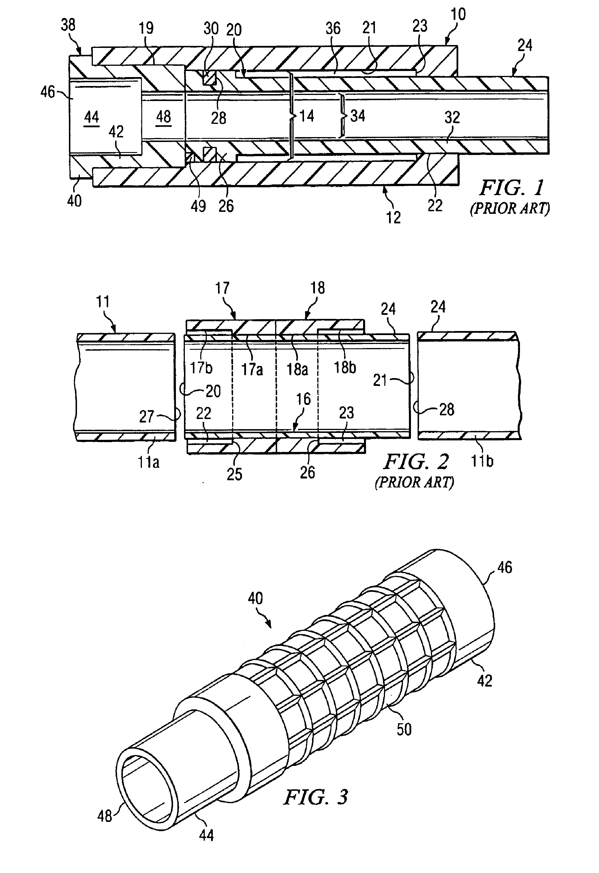
[0036]FIG. 1 and FIG. 2 are prior art devices for repairing damaged pipe sections in irrigation systems and other underground installed pipe systems. FIG. 1 is a cross sectional view of a pipe repair coupling (shown in FIG. 2 thereof) from the patent of Zimmerman U.S. Pat. No. 4,687,232 employing a telescopically extendable connection to facilitate repair.

[0037] In FIG. 1 Zimmerman teaches slip joint style pipe repair coupling 10 having a joint housing 12 containing a Piston pipe 24 extendable from one end thereof and a reducer bushing 38 mounted on its opposite end. Joint housing 12 includes an axial bore 14 containing piston pipe 24 so that is may move in a telescopic motion therein. Piston pipe 24 has an enlarged piston section 26 at its innermost end with an o-ring 30 providing sealing contact between piston portion 26 and axial bore 14. Joint housing 12 has a bushing socket 19 at one end to contain reducer bushing 38. Reducer bushing 38 has a two stage axial bore 44 to afford ...


PUM


Abstract

A unitary conduit repair joins first and second conduits each having open ends spaced from one another a predetermined distance, wherein the repair includes a unitary tubular body having a first end portion with an elongated female portion and an opposite second end portion with a male portion, and the unitary body has a total length greater than the predetermined distance between the ends of the first and second conduits.

Description

[0001] This patent application is related to application Ser. No. 10 / 985,370, filed Nov. 10, 2004, now abandoned, and application Ser. No. 10 / 074,924, filed Feb. 14, 2003, now abandoned, and Disclosure Document 471014 deposited on Mar. 17, 2000.TECHNICAL FIELD [0002] This invention relates to a simple unitary, conduit repair fitting, for repair of a damaged conduit and its associated connection to a valve or the like wherein a small section of the conduit is removed and an elongated female portion of the conduit repair fitting is slid over a first open end of the damaged conduit and subsequently extended into a female portion located at the end of the second conduit open end to complete the connection. An adhesive is used to secure the conduit repair fitting to the damaged first conduit to the end the second conduit. The invention also relates to a method of repairing damaged conduits wherein a unitary conduit repair fitting with a pre-glued interior elongated female portion and pre...

Claims


Application Information

Patent Timeline
Patent Type & Authority Applications(United States)
IPC IPC(8): F16L55/18
CPCF16L55/1608
Inventor BRYAN, HUGHES LANE
Owner BRYAN HUGHES LANE
Learn More