Modular boiler control

a boiler control and module technology, applied in the field of module boiler control, can solve the problems of increasing requiring removal of control wiring, and requiring modification or replacement of existing external control, so as to facilitate the addition of boilers, reduce the cost of installation, and facilitate the effect of adding boilers

a boiler control and module technology, applied in the field of module boiler control, can solve the problems of increasing requiring removal of control wiring, and requiring modification or replacement of existing external control, so as to facilitate the addition of boilers, reduce the cost of installation, and facilitate the effect of adding boilers

US20070295830A1Active Publication Date: 2007-12-27WESTCAST

Image

  • Modular boiler control
  • Modular boiler control
  • Modular boiler control

Examples


Embodiment Construction

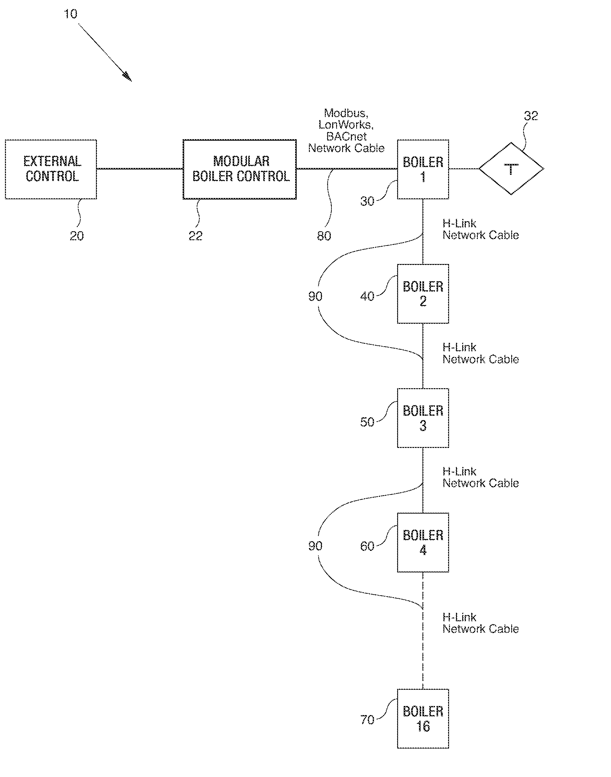
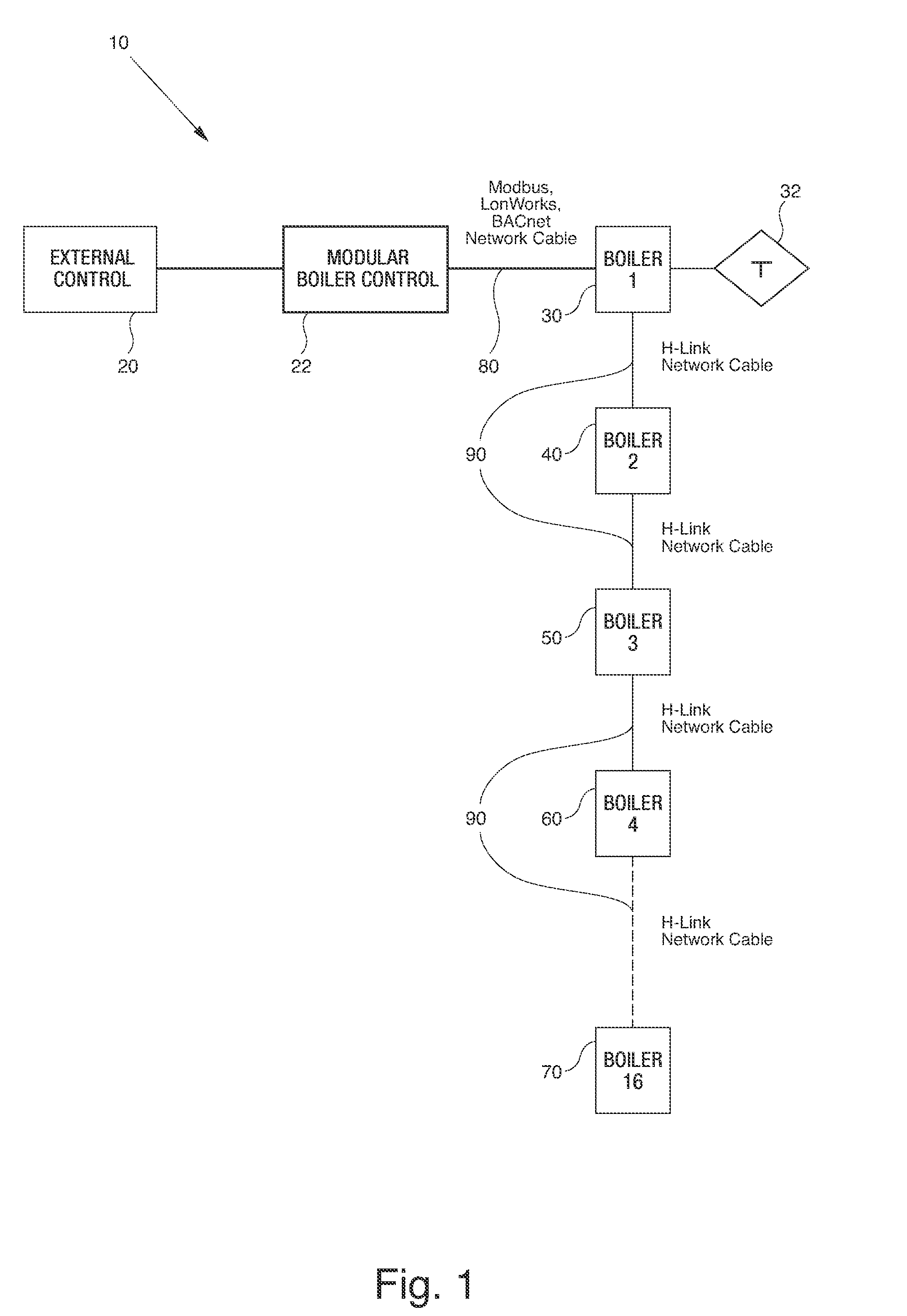
[0024]FIG. 1 is a simplified schematic illustration of a multiple boiler system 10 featuring a modular boiler control 22 according to one embodiment of the present invention. As shown in FIG. 1, the system 10 includes an external control 20 such as a building management system or a thermostat, a modular boiler control 22, and multiple individual boilers 30, 40. The external control 20 is connected to a first boiler 30 via a network cable 80. The first boiler 30 is also operatively connected to a temperature sensor 32. In the system shown in FIG. 1, the first boiler 30 is the “master boiler” as it is operatively connected to the system temperature sensor 32. The remaining secondary boilers, i.e., the “slave boilers”40 are serially connected to the master boiler 30, and to each other, by way of network cables 90. The master boiler is, by definition, the boiler connected to a system temperature sensor. As will be appreciated, the master boiler does not need to be the boiler directly co...


PUM


Abstract

A modular boiler system includes a boiler control, a first boiler in operative connection with the boiler control, and a temperature sensor in operative connection with the first boiler. The system also features at least one secondary boiler in operative connection with the master boiler. The boiler control is operatively connected to only the first boiler and it enables the first boiler to control a boiler parameter of the first boiler and the at least one secondary boiler.

Description

CROSS REFERENCE TO RELATED APPLICATIONS[0001]This application claims the benefit of U.S. Provisional Application Ser. No. 60 / 805,629, filed on Jun. 23, 2006, herein incorporated by reference in its entirety.FIELD OF THE INVENTION[0002]This invention relates generally to a modular boiler control, and more particularly to a modular boiler control in which a master boiler is networked with a least one slave boiler to control the heating loop of a structure.BACKGROUND OF THE INVENTION[0003]Known boiler systems include a boiler connected to an external control such as a thermostat or a building management system. The external control typically senses boiler temperature, controls boiler setpoint, performs outdoor reset functions and controls the boiler firing cycle.[0004]In multiple boiler systems, each boiler is connected to a single centralized external control from which all boiler operations are performed. The centralized control typically performs the above-listed functions for each ...

Claims


Application Information

Patent Timeline
27 Dec 2007
Publication
US20070295830A1
IPC
F24D19/10
CPC
F23N2037/02; F23N2041/04; Y02B30/14; F24D2200/043; Y02B30/108; F24D12/02; F23N2237/02; F23N2241/04
Inventors
COHEN, KENNETH W.; OSIENSKI, RICHARD