Automatically lockable cable rewinding structure

Inactive Publication Date: 2007-12-27
HONG WEN CHENG +1
View PDF8 Cites 27 Cited by
  • Summary
  • Abstract
  • Description
  • Claims
  • Application Information

AI Technical Summary

Benefits of technology

[0009]A primary object of the present invention is to provide a cable rewinding structure that enables a cable wound therein to be smoothly pulled out and locked in place, and smoothly rewound from a locked state simply by pulling and releasing the cable.
[0011]A further object of the present invention is to provide a cable rewinding structure that enables a rolling element to roll in a guide path without causing easy wearing of the guide path.
[0013]A still further object of the present invention is to provide a cable rewinding structure that has simple structure.
[0014]A still further object of the present invention is to provide a cable rewinding structure, the operation of which would not cause any adverse influence on the usable life of the cable wound therein.
[0015]To achieve the above and other objects, the present invention provides an automatically lockable cable rewinding structure that includes an upper case provided with a first locating element; a working member provided with a second locating element, and a guide path for a rolling element to move therein; and a lower case provided on a bottom with a limiting recess. A length of cable is wound around the working member, and an elastic element is connected at inner and outer ends to the first and the second locating element. The limiting recess is formed at radially inner and outer ends with transverse inner and outer slits, respectively, and between the inner and the outer slit with a longitudinal central slit, so that the rolling element is able to stably roll to and fro in the limiting recess along the central slit. Alternatively, the limiting recess and the guide path may be provided on the working member and the lower case, respectively. With the cable rewinding structure of the present invention, cables may be conveniently and orderly collected and stored.

Problems solved by technology

The following disadvantages are found in the above-mentioned conventional cable rewinding structures:(1) A clearance must exist-between the ball and a limiting recess.
Due to the clearance, the ball is not able to regularly move in the limiting recess and tends to skid off a locking section in the guide path.(2) When the ball fails to regularly and smoothly move in the guide path, the spiral spring tends to gradually become fatigued in its elastic strength, and the usable life of the cable is adversely affected.(3) When the ball fails to regularly and smoothly move in the guide path, the guide path tends to become worn easily, and the cable could not be smoothly rewound to adversely affect the usable life thereof.

Method used


Image

  • Automatically lockable cable rewinding structure
  • Automatically lockable cable rewinding structure
  • Automatically lockable cable rewinding structure

Examples


first embodiment

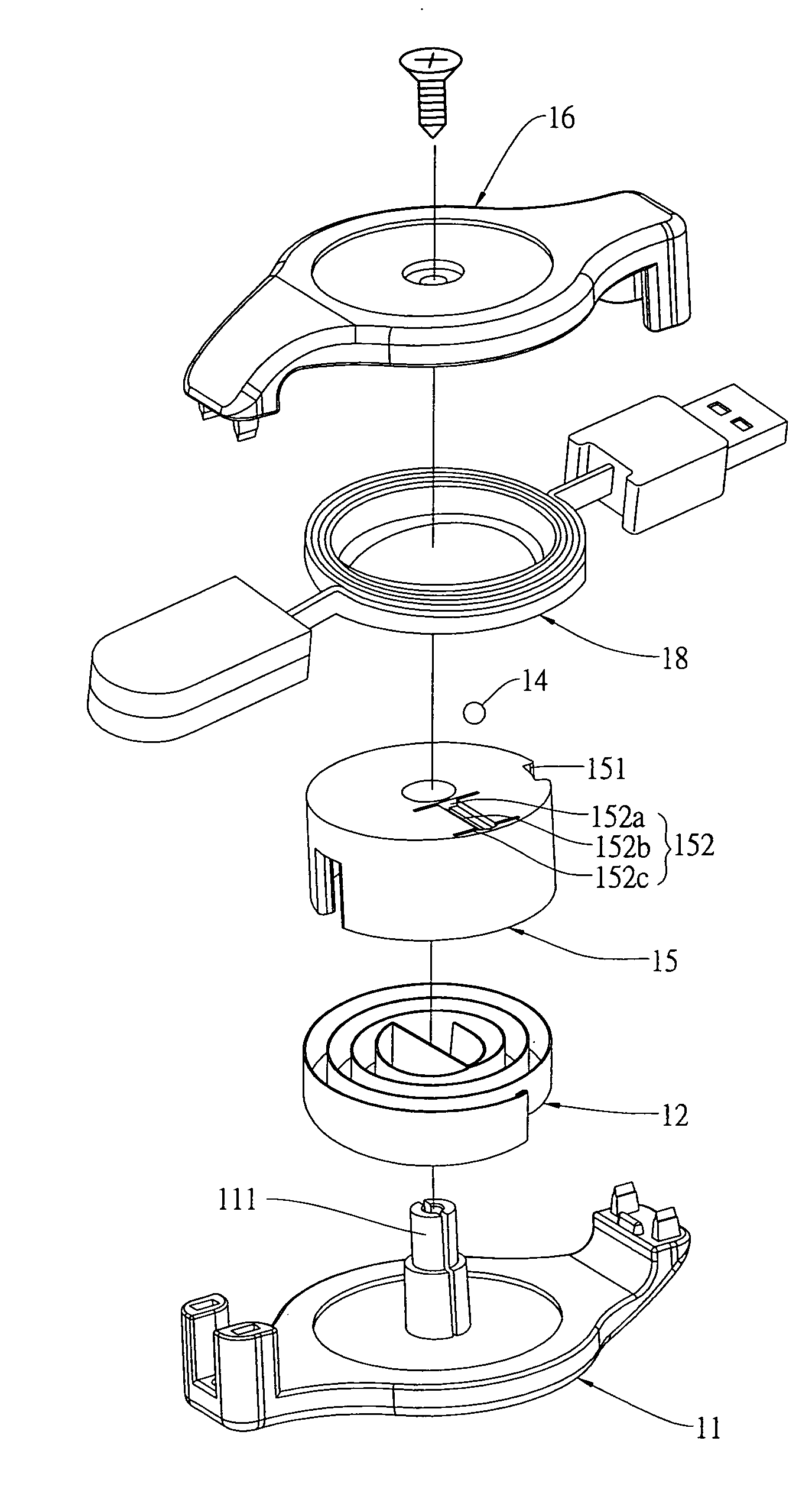
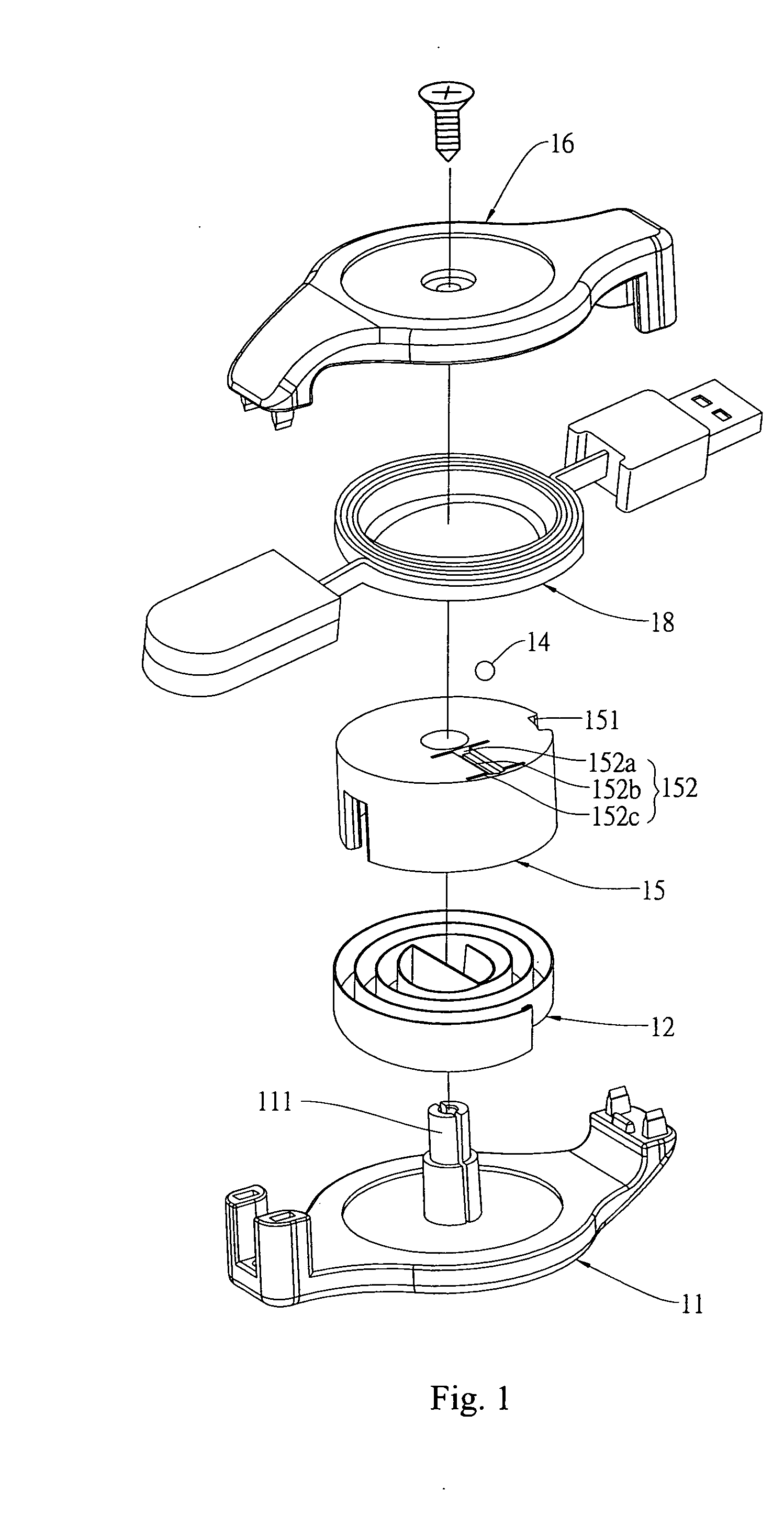
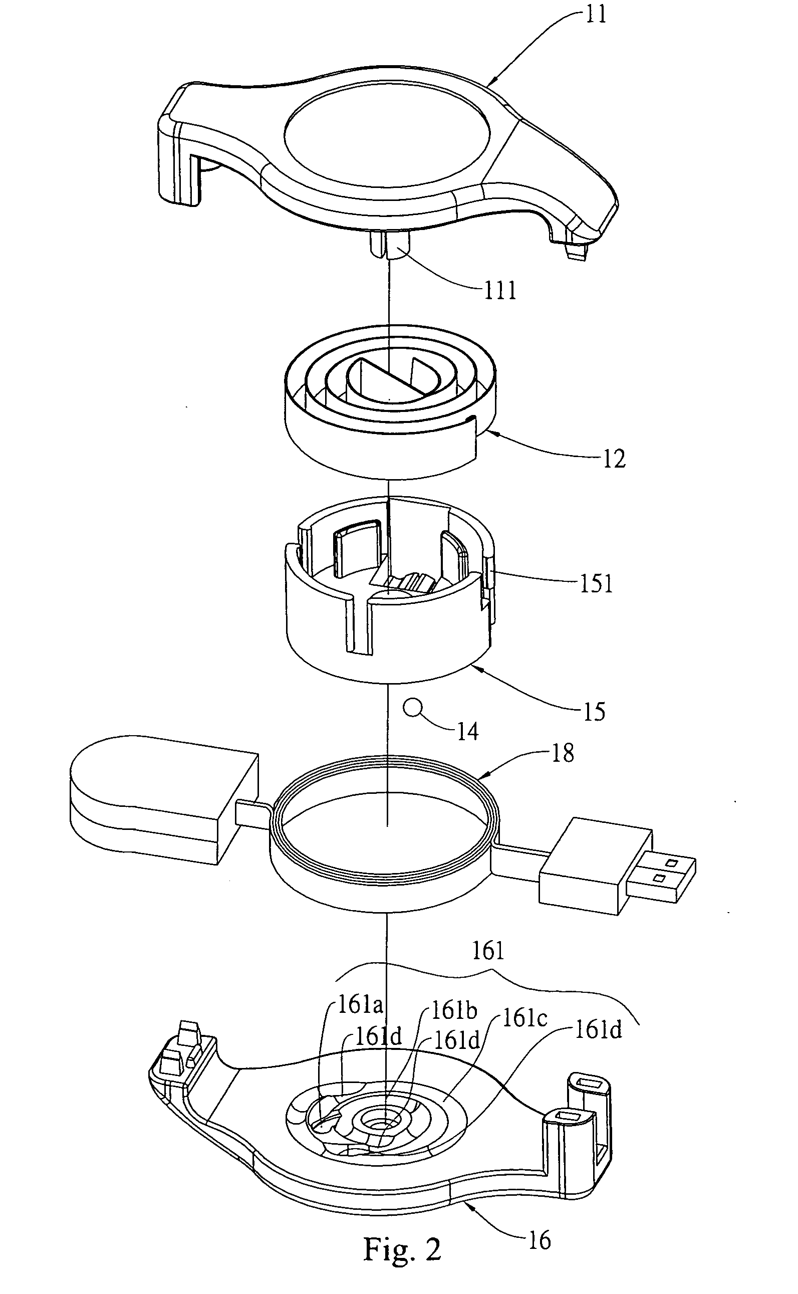
[0038]With the above arrangements, the automatically lockable cable rewinding structure according to the present invention is able to successfully lock or rewind the cable 18 through the following operating procedures.

[0039](a) Pull Procedure 1:[0040]Please refer to FIGS. 1, 2, and 4A at the same time.

[0041]It is noted the cable 18 can be pulled out of the assembled upper and lower cases 11, 16 in two opposite directions. When the cable 18 is pulled out in two opposite directions, the working member 15 is caused to turn counterclockwise, and the rolling element 14 is caused to move in the inner path section 161b.

[0042](b) Pull Procedure 2:[0043]Please refer to FIGS. 1, 2, and 4B at the same time. When the cable 18 is kept pulling out to turn the working member 15 counterclockwise, the rolling element 14 would move from the inner path section 161b through the transition sections 161d into the outer path section 161c. At this point, the limiting recess 152 at the bottom of the workin...

third embodiment

[0062]With the above arrangements, the automatically lockable cable rewinding structure according to the present invention is able to successfully lock or rewind the cable 38 through the following operating procedures.

[0063](a) Pull Procedure 1:[0064]Please refer to FIGS. 7, 8, and 10A at the same time. It is noted the cable 38 can be pulled out of the assembled upper and lower cases 31, 36 in only one direction. When the cable 38 is pulled out at an end thereof, the working member 35 is caused to turn counterclockwise, and the rolling element 34 is caused to move in the inner path section 352b.

[0065](b) Pull Procedure 2:[0066]Please refer to FIGS. 7, 8, and 10B at the same time. When the cable 38 is kept pulling out in the same direction to turn the working member 35 counterclockwise, the rolling element 34 would move from the inner path section 352b through the transition sections 352d into the outer path section 352c. At this point, the limiting recess 362 at the bottom of the l...


PUM


Abstract

An automatically lockable cable rewinding structure includes an upper case having a first locating element; a lower case provided with a limiting recess; and a working member located between the two cases, and provided with a second locating element and a guide path for a rolling element to move therein. A length of cable is wound around the working member, and an elastic element is connected at two ends to the first and second locating elements. The limiting recess is formed at radially inner and outer ends with transverse inner and outer slits, respectively, and between the inner and the outer end with a longitudinal central slit, so that the rolling element is able to stably roll to and fro in the limiting recess along the central slit. Alternatively, the limiting recess and the guide path may be provided on the working member and the lower case, respectively.

Description

FIELD OF THE INVENTION[0001]The present invention relates to an automatically lockable cable rewinding structure, and more particularly to a cable rewinding structure that enables a cable wound therein to be smoothly pulled out and locked in place and smoothly rewound from a locked state simply by pulling and releasing the cable.BACKGROUND OF THE INVENTION[0002]Taiwanese New Utility Model Patent No. 414413 published on Dec. 1, 2000 discloses a cable rewinding box, which includes an upper cover, a lower cover, a rotating base, a rotating disc, a constant force spring, and a fixing shaft. With the constant force spring, the cable pulled out of the rewinding case may be automatically rewound. Generally speaking, the constant force spring may provide a relatively stable contractile tension, and can therefore protects the cable against damage and shortened usable life caused by exceeded tension. Since the constant force spring and the rotating disc are provided at different axial locatio...

Claims


Application Information

Patent Timeline
IPC IPC(8): B65H75/48
CPCB65H2701/34B65H75/4434H02G11/02B65H75/406B65H75/4402
Inventor LIN, YAO-CHENG
Owner HONG WEN CHENG
Why Eureka
Try Eureka