
Generator start/stop controller

a technology of start/stop controller and generator, which is applied in the direction of electric generator control, motor/generator/converter stopper, dynamo-electric converter control, etc., can solve the problems of virtually impossible to predict where and when refueling is required, frozen contents of containers at risk of perishing, and constant operation of generator consumes the entire 130 gallons of fuel, so as to achieve cost reduction, energy and equipment saving, and a cleaner environment

Active Publication Date: 2007-12-27
GENDRON JACK DELBERT
View PDF5 Cites 22 Cited by
  • Summary
  • Abstract
  • Description
  • Claims
  • Application Information

AI Technical Summary

Benefits of technology

[0015]It is, therefore, an object of the present invention to provide a generator start / stop controller that uses an ambient temperature sensor rather than an in-box sensor in addition to a programmed microprocessor to regulate the operation of the generator. When the container is transported through an area where the ambient temperature is the same as or less than the required in-box temperature, the generator is automatically turned off completely. This contributes enormously to cost, energy and equipment savings and provides a cleaner environment.
[0016]In addition, it is an object of the present invention to provide a generator start / stop controller that uses pre-calculated settings and programming to automatically turn the generator back on, not simply when the ambient temperature is the same as or greater than the required in-box temperature, but only when the container has experienced a period of time in a high heat zone sufficient to compromise the required in-box temperature and the quality of the frozen goods in transport. This further contributes to cost, energy and equipment savings and also a cleaner environment.
[0017]The invention proposes to avoid having to provide an in-box temperature sensor and an electrical conductor for the temperature sensor connected between the container and the generator as is the case with in-box temperature sensing systems. This is especially advantageous on a railway system where several refrigerated containers are operated via individual power cords from a single generator / compressor unit. These power cords must provide a separate conductor dedicated to the temperature sensor. Since ambient temperature is used in the present invention to control the run-time of the generator, the temperature sensor may be installed with the controller directly on the generator unit and the separate temperature sensor conductor is not required. In addition to cost savings in the reduced quantity of sensors and conductors required per generator unit, there are installation, maintenance, and operational advantages, as well.

Problems solved by technology

On most cross-country rail or roadway trips, continuous operation of the generator consumes the entire 130 gallons of fuel well before the container's destination.
Since containers begin and end their routes from various locations, it is virtually impossible to predict where and when refueling is required.
Quite often, along the route, a generator dies for lack of fuel and does not get refueled and restarted and the frozen contents of the container are at the risk of perishing.
It is well known that the circulating fans in the container have minimal effect in efficiently moving chilled air to every part of a container fully loaded with frozen goods.
It is also well known that circulating fans generate a significant amount of BTUs / min., thereby counterproductively contributing to the raising of the in-box temperature.
In addition, should the compressor experience failure during transit, the fans, since they are not controlled by the in-box temperature sensor, would continue to run and ultimately raise the in-box temperature to a point where the frozen goods would perish.
It is, therefore, questionable that the continuous operation of the circulating fans is justified considering: (1) the amount of fuel and expense required to operate the generator when it is operating solely to power the fans; (2) the effectiveness of the fans; (3) the fact that the fans themselves, when operating, contribute to raising the in-box temperature, thereby decreasing the overall efficiency of the refrigeration system, and; (4) the risk of loosing a load of perishable goods if the compressor were to fail in transit.
This is especially questionable, when the container is transported through an area of the country where the ambient temperature is the same as or below the required in-box temperature.
While the generator is operated during this period: (1) generator running time and its associated maintenance costs, man power and fuel consumption are a total waste, and; (2) the environment is unnecessarily contaminated.
None of these, however, have addressed the serious problem of generators that are operating unnecessarily.

Method used


Image

  • Generator start/stop controller
  • Generator start/stop controller

Examples


Embodiment Construction

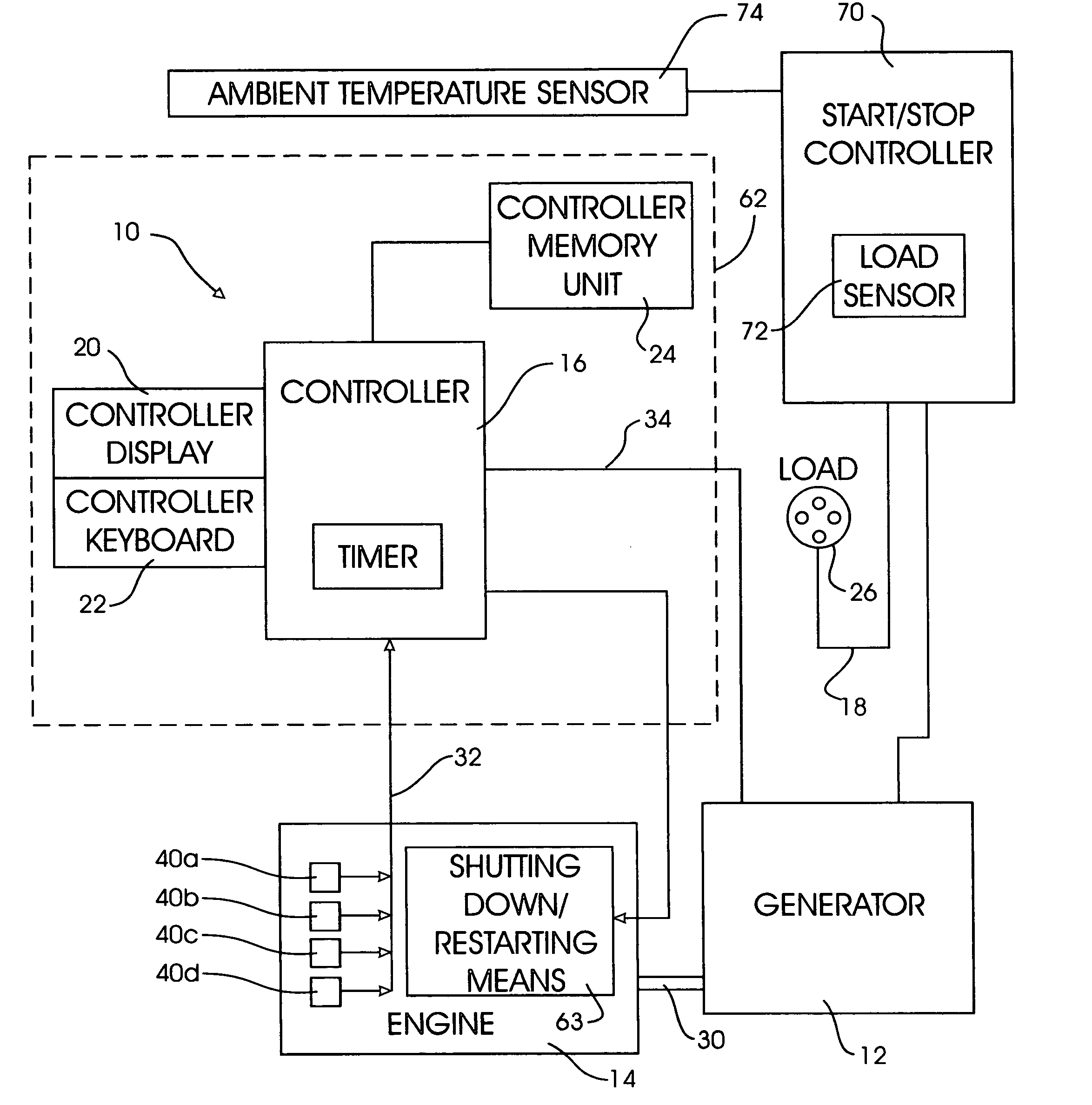
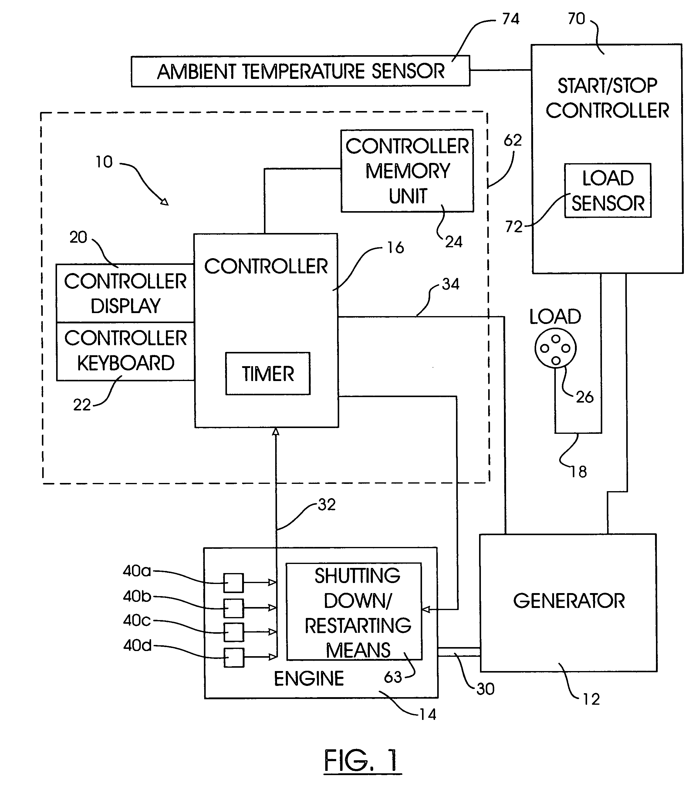
[0021]Referring now to FIG. 1, a generator set 10 in accordance with the present invention is shown in block drawing form. Generator set 10 includes three principle components, a generator 12, engine 14 and a controller 16. The controller is enclosed by enclosure walls 62 represented in a dash-lined box in FIG. 1.

[0022]Engine 14 is preferably an industrial duty diesel engine. Such an engine would include a cooling system, an oil lubricant system, an electrical system including a battery, an alternator and glow plugs. Its fuel system would include a fuel tank and a fuel solenoid for controlling the flow of fuel to the cylinders. A drive shaft 30 transfers energy from the engine to the generator. The engine 14 also includes means for shutting down and restarting the engine 14. The shutting down / restarting means is identified generally at 63 in FIG. 1. The shutting down / restarting means 63 is collectively comprised of well known electronically actuated components such as a fuel valve a...


PUM


Abstract

A method and apparatus is disclosed for starting and stopping a generator set that supplies power to a refrigeration system. An ambient temperature sensor is used rather than an in-box sensor in addition to a programmed microprocessor to regulate the operation of the generator. Unnecessary use of the generator is, thereby, limited which contributes to cost, energy and equipment savings and a cleaner environment while ensuring the required in-box temperature is maintained and the quality of perishable goods are not compromised.

Description

BACKGROUND OF THE INVENTION [0001]The present invention relates generally to a method of controlling a refrigeration system. More particularly, the invention relates to a method of controlling the start / stop of a generator that powers a refrigeration system used on containers transporting frozen goods via rail or roadway.[0002]It is common in the field of transport refrigeration to control the start / stop of the generator and thereby, the compressor (refrigeration system) and circulating fans by monitoring the temperature of the inside of the container with an in-box temperature sensor.[0003]In a typical system, frozen goods at 0 degrees Fahrenheit are loaded into an insulated refrigeration container destined for transit by ship, railcar or truck. Each container is supplied with its own independent refrigeration system and circulating fans. The system and fans are designed with sufficient capacity to maintain a pre-set box temperature of varying degrees F. for the duration of the tri...

Claims


Application Information

Patent Timeline
IPC IPC(8): H02H7/06H02P11/00H02P9/00F02N99/00
CPCH02P11/00H02P9/08F25B27/00F25B2500/26F25B2500/27F25B2700/2106B60H1/3226B60H1/3232B60H2001/3273
Inventor GENDRON, JACK DELBERT
Owner GENDRON JACK DELBERT
Learn More